En
En 
Introduction
What a line follower robot is and how it works
A line follower is an autonomous robot that drives along a line on the floor — usually black on white — as fast and as precisely as it can. Building a line follower robot is one of the best first projects in robotics: it has every part of a real robot, and you see at once whether your code works.
Line following is part of the Georgian Robotics Association's (GRA) school competitions (the zigzag task), and the Georgian Robotics Championship has its own Line Follower category — see how to start robotics at school and the 2026 championship. Here we build our own robot and teach it to drive smoothly with PID. New to robotics? Start with my first robot.
In short: the sensors measure where the line is, the controller turns that into one number — the error — and speeds up one wheel and slows the other until the error is zero again, hundreds of times a second.
The parts of a line follower robot
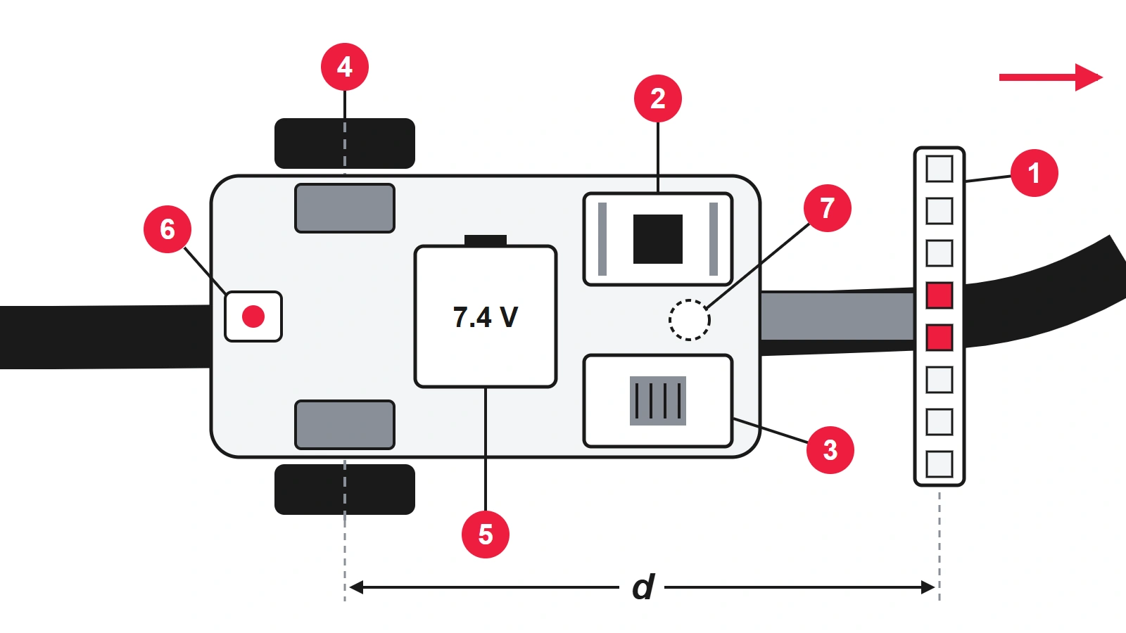
The parts — the numbers match the diagram:
- IR sensor array — 5–8 reflectance sensors in a row at the front (TCRT5000 or QTR-style). More sensors mean a more precise position.
- Controller — an Arduino Nano/Uno-class board is plenty to start; an ESP32 or STM32 board runs a faster loop later.
- Motor driver — a controller pin cannot power a motor. A MOSFET driver (TB6612FNG or DRV8833 type) wastes far less voltage than the old L298N.
- Two gear motors with wheels — N20 gear motors are the classic choice, better still with encoders; rubber tyres grip best.
- Battery — a 2S LiPo (7.4 V) or two 18650 cells with a protection board; AA cells do for a first, slow version.
- Power switch — between the battery and everything else.
- Ball caster — the third support point, with little friction.
Add a light, stiff chassis (3 mm plywood or acrylic, or a 3D-printed plate), wires and screws. A light and low robot is easier to control than a powerful, heavy one.
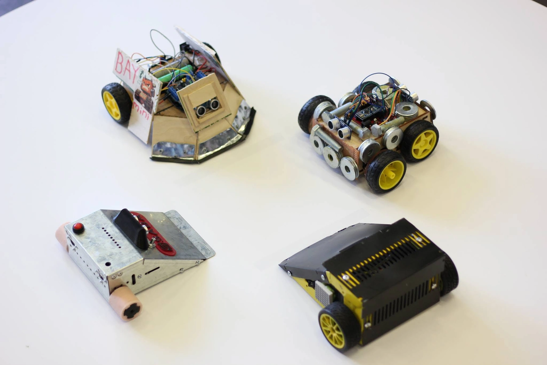
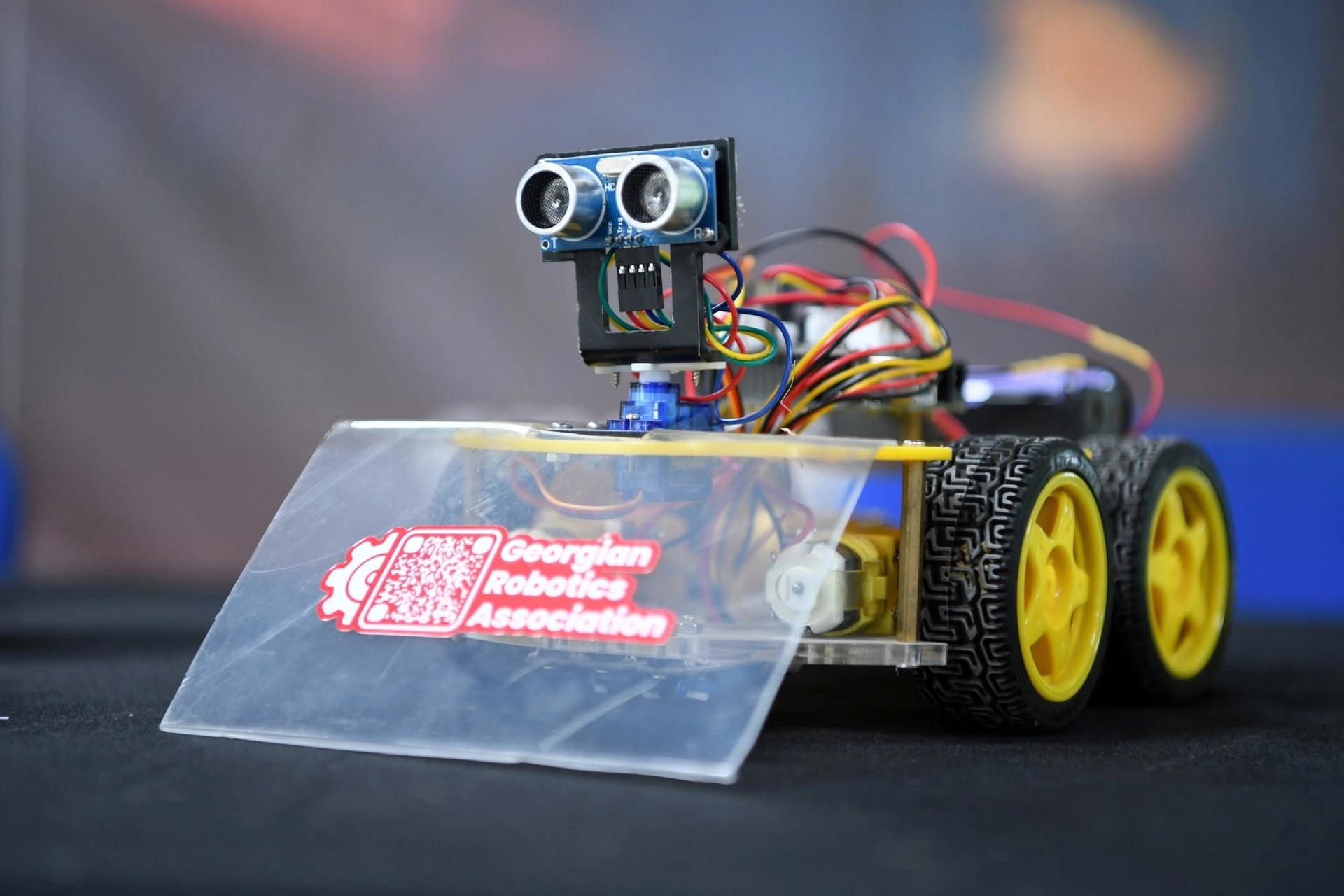
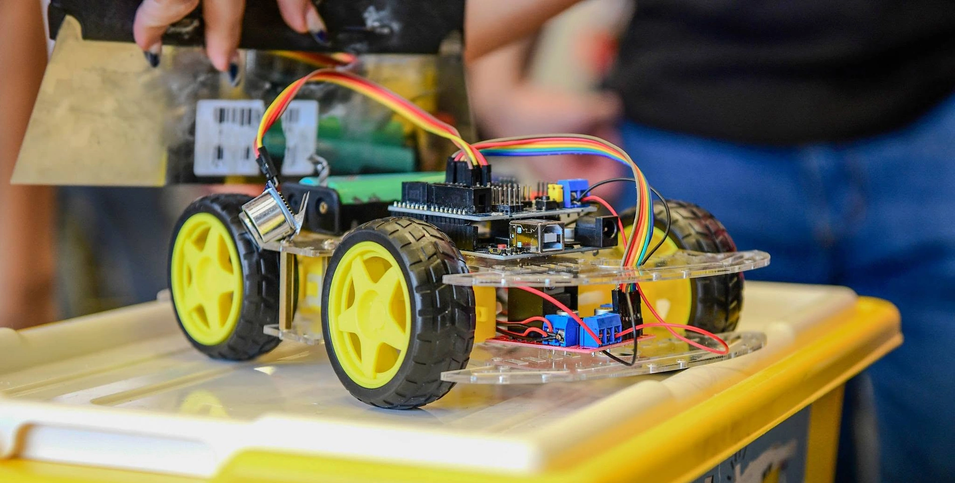
School line followers: many school teams start with a kit — at our first school competitions teams used mBot and the 4WD Smart Robot Car. Kits already have motors and line sensors; the calibration and PID below work on them too. In GRA's 2026 school rules the robot may weigh up to 1 kg and must fit in a 180 × 280 mm box.
How the robot sees the line: IR sensors and the error
Each sensor has an infrared LED and a phototransistor: a white surface reflects infrared light, black absorbs it. Read the analogue value (0–1023 on an Arduino), not just a digital yes/no — then the robot sees positions in between too.
- Height — most reflectance sensors work best a few millimetres above the surface (about 2–8 mm; see the datasheet). Keep it constant.
- Spacing — about 8–12 mm, so that a 15–20 mm line always covers one or two sensors (GRA's 2026 school rules: a 1.6 cm line).
- Calibration — before the start, sweep the sensors over line and background, store each one's minimum and maximum and scale every reading to 0–1000; this evens out the sensors and the lighting.
- Error — give each sensor a weight (−3 to +3 for 7 sensors) and take the weighted average: e = Σ(w·s) / Σs. In the diagram: 1 — line under the centre, e = 0, straight on; 2 — between +1 and +2, e = +1.5, turn right; 3 — far left, e = −3, turn hard left.
- Lost line — if every sensor sees background, turn hard towards the side of the last error.
- White line on black — GRA's 2026 school rules allow a black or a white line on a contrasting background, so make inversion one setting in your code (s = 1000 − s).
Assembly and wiring, step by step
- Mount the two motors symmetrically, with the wheels parallel.
- Mount the sensor array at the front — rigidly, at the tested height, across the direction of travel. Distance d from the wheel axle (first diagram): a longer d sees curves earlier but swings more; 5–10 cm suits a small robot.
- Put the battery low and close to the axle, so that little weight rests on the caster.
- Power: battery → switch → motor driver, and → regulator → controller. Connect all grounds (GND) together.
- Signals: sensors → analogue inputs; the driver's PWM and direction pins → controller; motors → the driver's outputs.
- First test with the wheels in the air: watch the sensor values in the serial monitor and check each motor's direction (if wrong, swap its two wires).
Safety:
- Soldering — the iron in its stand, a ventilated room (flux fumes), safety glasses; wash your hands after leaded solder. The tip is about 300–350 °C.
- LiPo — a balance charger only, never unattended, in a fire-safe bag; never below about 3.3 V per cell; a swollen battery is retired and never punctured.
- Short circuits — check the polarity before the first switch-on; a fuse saves many boards.
PID control explained simply
The simplest logic is on/off ("bang-bang"): the line is on the left — turn left; on the right — turn right. It works, but the robot wobbles and has to drive slowly.
PID computes a smooth correction (u) from the error (e) in every loop. In the diagram: 1 — the sensors measure the line's position (x), and the error is its distance from the centre (0); 2 — PID; 3 — motor mixing; 4 — the motors; 5 — the robot moves and the sensors see a new position. The correction has three parts:
- P (proportional) — Kp·e: the further from the line, the harder the turn. Too small — lazy in curves; too big — oscillation.
- D (derivative) — Kd·Δe, that is Kd·(e − previous e): it reacts to how fast the error changes and damps the wobble — this is what lets a line follower go fast.
- I (integral) — Ki·Σe: it corrects a small steady offset (say, one weaker motor); in line followers it is often tiny or zero.
Motor speeds (block 3): L = b + u, R = b − u, where b is the base speed; limit the result to the PWM range (0–255 on an Arduino). Keep the loop interval fixed (Δt, e.g. 2–5 ms) so that D and I stay consistent. If the robot steers away from the line, flip the sign of u.
Tuning PID, step by step
1. Charge the battery fully and tune on a surface like the competition's.
2. Ki = 0, Kd = 0, and a low base speed (about 30–40 % of maximum).
3. Raise Kp slowly until the robot follows the curves and just starts to wobble on the straights.
4. Raise Kd until the wobble disappears — Kd often ends up much larger than Kp.
5. Add a little Ki only if the robot keeps running to one side of the line on the straights.
6. Raise the base speed in small steps, re-tuning Kp and Kd each time, and write everything down.
Typical problems: the wobble grows with speed — add Kd; the line is lost in sharp corners — slow down when the error is large; different every day — recalibrate on site and check the battery; wheels slip — wipe the tyres.
A test track at home or at school
- Surface — a white matte board, plywood painted white, or thick paper sheets taped together from below. Avoid gloss — reflections confuse the sensors.
- Line — black electrical tape 15–20 mm wide (GRA's 2026 school rules use 1.6 cm). Lay curves in short pieces.
- Elements — a long straight, wide and tight curves, a sharp zigzag, an S-curve, and start and finish lines.
- Inversion — a short piece with a white line on black: the school rules allow both.
- Timing — time every run from the start line to the finish line and keep a notebook: Kp, Ki, Kd, base speed, battery voltage, time.
- Start — practise the button start too: in GRA's 2026 school rules the robot must start moving within 5 seconds of the button being pressed.
What next
- The basics — my first robot; the same parts for a different task — how to build a SUMO robot.
- For school teams — how to start robotics at school and the School Robotics Competition.
- For older pupils and students — the SUMO and Line Follower championship; how it went in 2026 — the championship report.
- Rules: every GRA championship publishes its current rules on its own page. A separate guide to line follower rules is coming soon.
- Every post on this topic — line follower; upcoming events.