En
En 
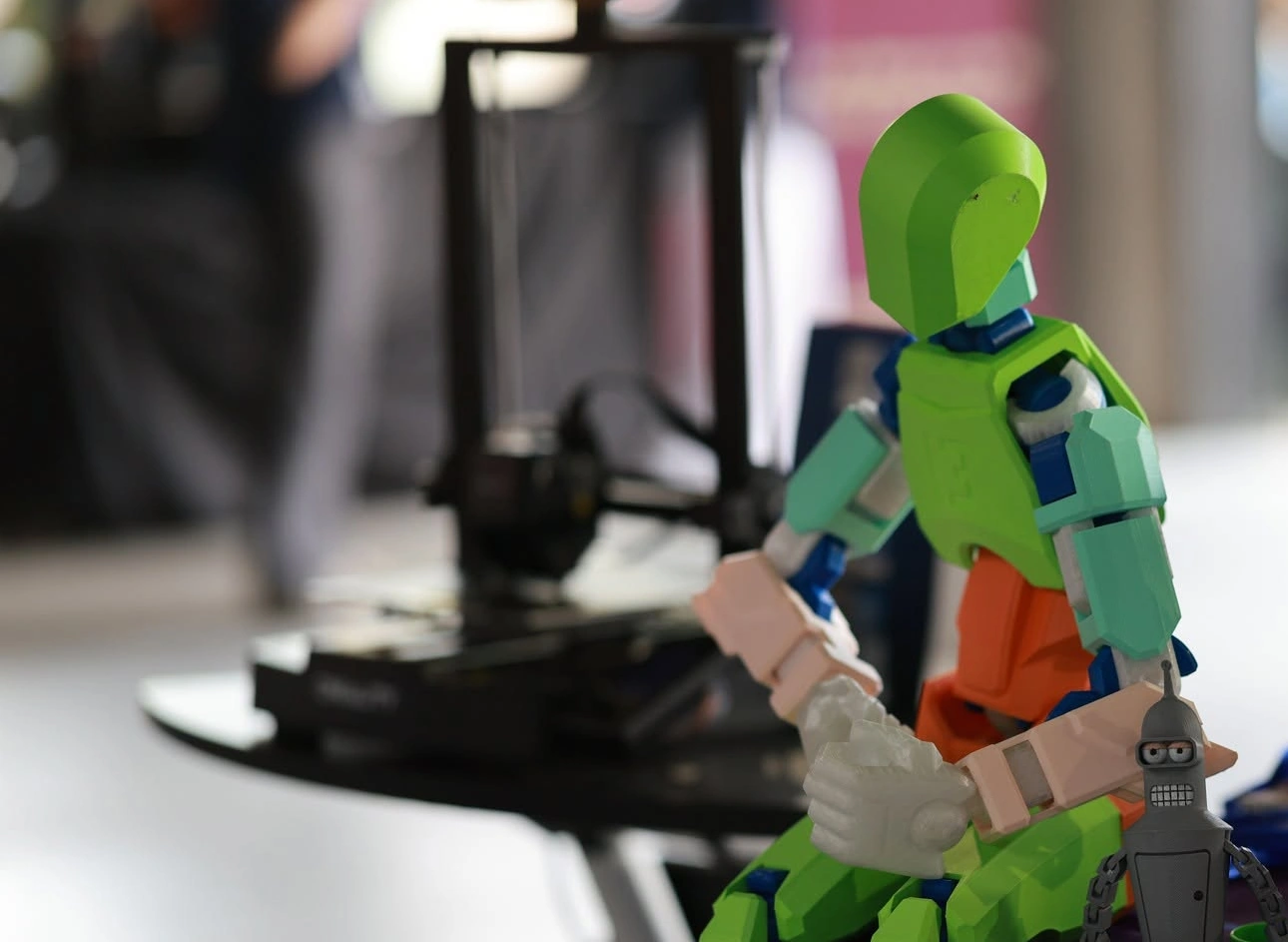
What to 3D print on a robot, and what not to
A 3D printer is one of the most useful tools in robotics: you draw a part on the computer and hold it in your hand a few hours later. The most common type, the FDM printer, melts a plastic thread (filament) and builds the part layer by layer. This guide shows how to make a 3D printed robot that survives a competition: which material to choose, which settings to use and what size to draw the holes.
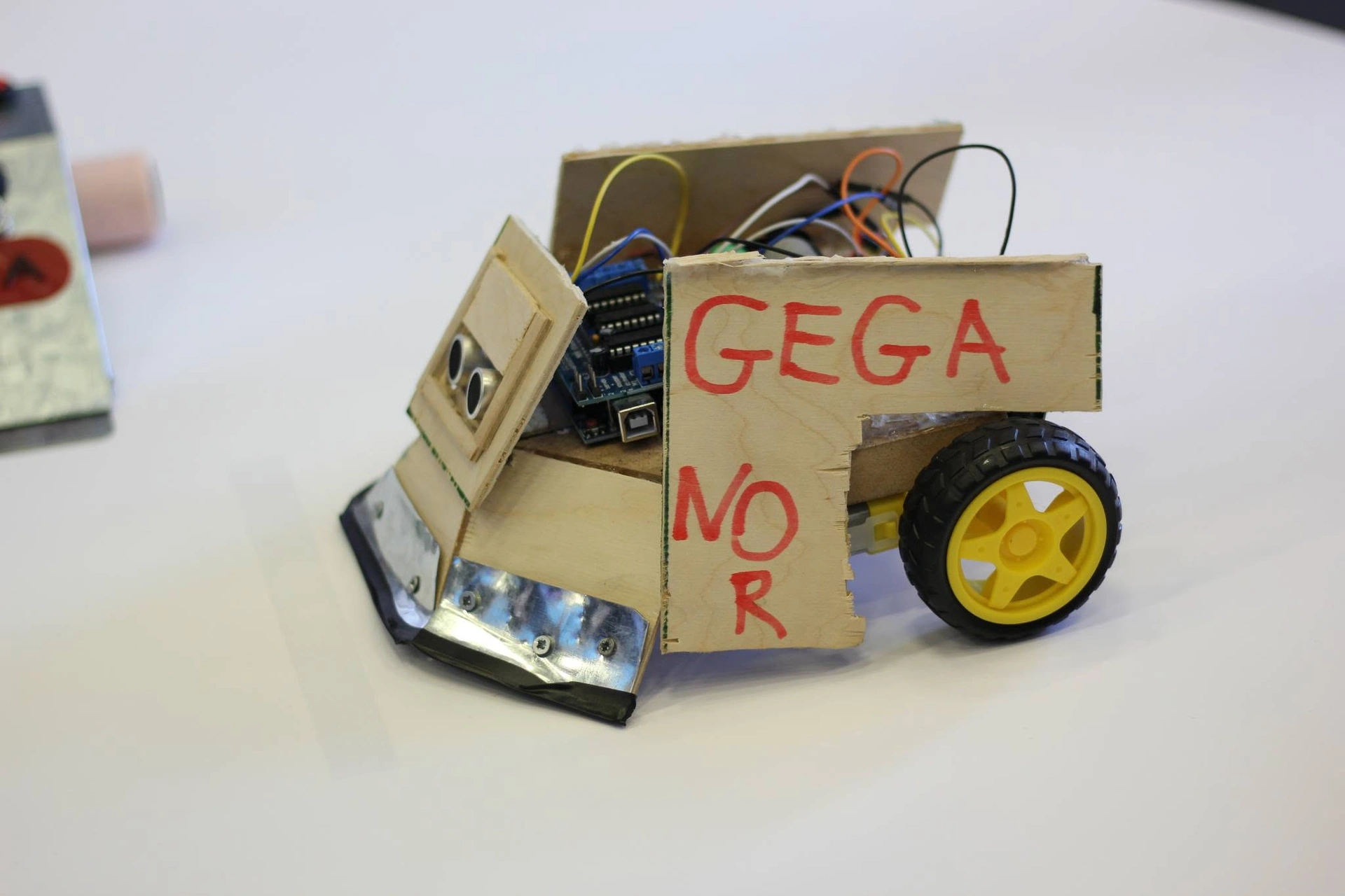
Good to print — robot parts that must fit your own robot exactly:
- the chassis and body of small robots (line follower, mini SUMO, school robot);
- motor mounts, sensor holders, wheel hubs;
- boxes for the battery, the motor controller (ESC) and the receiver, covers, bumpers.
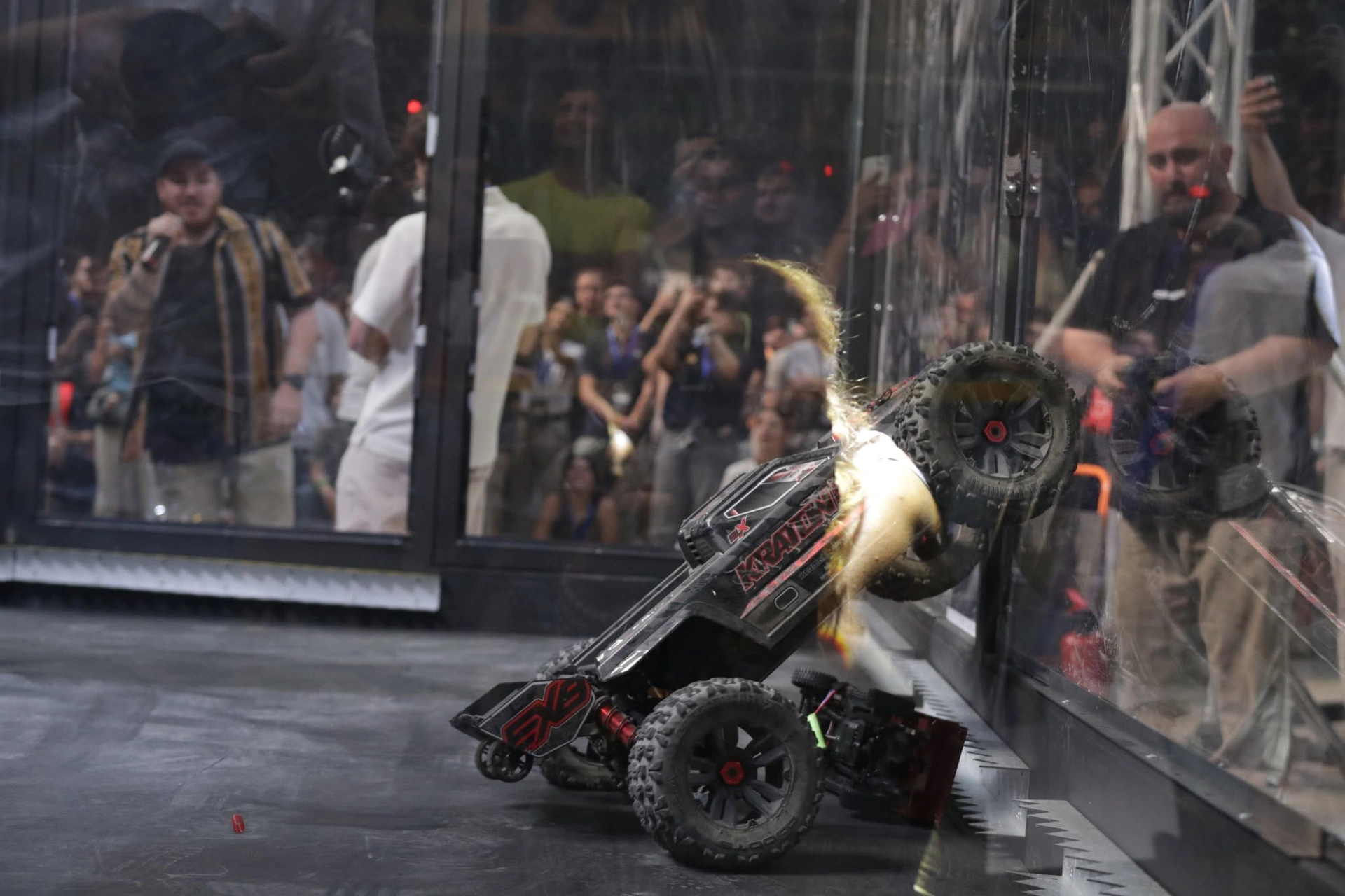
Better not to print what is better bought: shafts, bearings, screws, heavily loaded gears, parts next to a hot motor and a combat robot's spinning weapon. A typical solution (see the photo): a metal frame takes the hits, while printed boxes and brackets inside hold the electronics.
Starting from zero? Read My first robot first.
Materials: PLA, PETG, ABS, TPU and nylon
Choose the material for the job — the load and the temperature the part must take:
- PLA — the easiest to print, stiff and accurate, but brittle under impact and soft at about 55–60 °C (it can bend next to a hot motor). Good for prototypes, line followers and school robots.
- PETG — tougher and less brittle, takes about 75–80 °C. A good everyday choice, e.g. for a mini SUMO body.
- ABS / ASA — takes heat (about 100 °C) and impacts, but warps while printing: it needs an enclosed printer and good ventilation.
- TPU — a flexible, rubber-like material for tyres, bumpers and shock mounts; small combat robots also use it as armour because it absorbs hits.
- Nylon (PA) and carbon-fibre filled materials — very tough and wear-resistant, for gears and loaded mounts; fibre-filled filament needs a hardened nozzle.
PETG, TPU and nylon absorb moisture, and wet filament gives weak parts — keep it in a closed box with silica gel.
In GRA's 2026 ROBO BATTLE rules a combat robot may be made of metal, plastic, rubber and other materials, and hard rubber or plastic may be used on its exterior; if you are unsure about a material, ask the organisers first.
Orientation: the bond between layers is the weak spot
A printed part is not equally strong in every direction. Inside a layer the plastic lines are strong; between layers there is only a weld, and a part almost always breaks along a layer line. So the part's orientation on the print bed matters as much as the material.
In the diagram:
- layers — they stack up vertically while printing (the Z axis);
- the force (F) on the part;
- the crack — a peg printed standing up breaks between layers (✗);
- the print bed.
Print the same peg lying on its side and its layers run along its length — it takes the same load (✓). The rule is simple: the load must not pull the layers apart. Print an L-shaped bracket on its side so both arms lie on the bed, and a wheel hub flat.
The face on the bed comes out the flattest — use it for the surface that mounts a motor or a sensor. Overhangs steeper than 45° need supports, and the surface under them comes out rough.
Walls, infill and other settings
Strength comes mostly from the walls (perimeters) and the solid top and bottom layers, not from the infill inside. As a rule, going from 2 walls to 4 makes a part stronger than going from 20% to 50% infill.
In the diagram:
- walls — the outer outline, several lines side by side;
- the solid top and bottom layers;
- infill — the grid-like structure inside;
- a screw hole: the extra walls around it form a solid ring.
Starting settings for a 0.4 mm nozzle (then test them on your printer):
- layer height 0.2 mm; 0.12–0.16 mm for small, precise parts;
- walls 3–4 (1.2–1.6 mm); top and bottom layers 4–5;
- infill 20–40%, gyroid or cubic pattern;
- parts that take hits (a mini SUMO wedge mount, combat robot parts): 5 or more walls and 40–60% infill, small parts even 100%.
For good layer bonding, print in the upper half of the material's temperature range, turn the cooling down for PETG and ABS, and print the outer wall slowly for more accurate dimensions.
Tolerances: holes for motors, bearings and screws
A 3D printer doesn't reproduce sizes exactly: a printed hole usually comes out 0.1–0.3 mm smaller. So a hole is drawn a little bigger than the part that goes into it; this difference is the clearance.
In the diagram — starting values for the hole diameter:
- a bearing pressed in (press fit): + about 0.1 mm — e.g. 22.1 mm for a 608 bearing (22 mm);
- a turning shaft (sliding fit): + 0.2–0.3 mm;
- a screw passing through: + 0.3–0.5 mm — 3.3–3.4 mm for an M3 screw;
- the printed hole is smaller than the drawn one;
- a test plate with holes in 0.1 mm steps.
Every printer and material behaves differently, so print the test plate (point 5) and pick the hole your part fits — ten minutes that save hours of reprinting. Measure the motor with a caliper before you draw its mount — even small N20 gear motors differ from maker to maker.
Don't drive a screw you often undo straight into plastic: use a nut trap or a metal heat-set insert melted in with a soldering iron.
Printing robot parts: design, finishing and safety
A few rules make printing robot parts easier:
- round the inside corners (fillets) — cracks start easily in a sharp corner;
- keep walls at least 1.2 mm thick; add ribs instead of extra thickness;
- split a big chassis that doesn't fit on the bed into pieces and bolt them together;
- leave room for the wires and easy access to the switch and the battery.
Free programs (e.g. Tinkercad or FreeCAD) are enough for a beginner. Measure the bought parts first and put a simple "dummy" of each into your model.
Finishing: remove supports carefully, clean the edges with a knife or a file, drill the holes to size.
Safety:
- the nozzle heats up to 200–260 °C and the bed to 60–100 °C: hands off while printing;
- ABS and ASA give off harmful fumes: print in a well-ventilated room, not in a bedroom;
- cut supports away from yourself;
- don't leave long prints unattended; children should use the printer with an adult nearby.
A printed robot at a competition: size, weight and spare parts
Start from the class's size and weight. In GRA's 2026 rules:
- a mini SUMO robot must be no larger than 10.3 × 10.3 cm when it starts on the ring and weigh at most 0.505 kg (height is not limited); a mega SUMO must fit in a 20 × 20 cm square and weigh at most 3 kg;
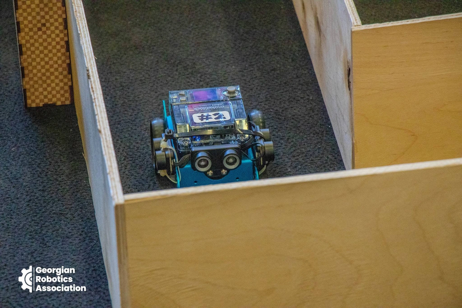
- a zigzag or labyrinth robot at the school competition weighs at most 1 kg and must fit in a 180 × 280 mm box — a chassis that uses the full 280 mm won't print in one piece on many printers, so split it;
- the lightest ROBO BATTLE classes are Antweight (500 g, a pilot class) and Beetleweight (1.5 kg) — where printed bodies and TPU armour are common.
Under the ROBO BATTLE 2026 rules a part may be replaced between battles only with an identical one (same shape, size and weight), agreed with the organisers, and spare parts must be shown at the technical inspection. So print your spares from the same file, material and settings, and weigh them.
Each championship publishes its current rules on its page — check them before you draw.
What next
- a SUMO robot step by step — How to build a SUMO robot;
- the line follower — the build and the competition rules;
- combat robots — what a combat robot must be like and first steps in building one;
- ROBO BATTLE 2026 takes place in November 2026, international for the first time and open to spectators;
- the association's events — on the events page; to take part with a team, volunteer or partner — get involved;
- every article about 3D printing — on the tag page.