En

The mini sumo robot among the weight categories
Sumo robots, like wrestlers, compete in weight and size classes. This is a mini sumo robot build at workshop level: your own printed circuit board (PCB), CNC machining, laser cutting, 3D printing, cast tyres and a hardened blade. The rules and our champion Kokadama are in the Mini Sumo article; for a first robot, start with the step-by-step guide. Our teams' results at RoboChallenge 2026 are here.
The first diagram shows the four sumo classes under RoboChallenge's 2026 regulations (robots on one scale at the top, their rings below):
- Mega Sumo — up to 3 kg (3005 g on the scale), 20 × 20 cm; a steel ring, Ø 154 cm, magnets allowed.
- Mini Sumo — under 500 g (up to 502 g on the scale), 10 × 10 cm, any height; a wooden ring, Ø 77 cm, with a 25 mm white border.
- Micro Sumo — under 100 g, 5 × 5 × 5 cm; ring Ø 38.5 cm.
- Nano Sumo — 25 g, a 2.5 cm cube; ring Ø 19.25 cm.
The dashed square is the homologation frame (10.2 cm for Mini). GRA's 2026 championship allowed 0.5 kg (0.505 kg on the scale), with magnets and vacuum banned. RoboChallenge bans fans and pumps too, and a robot small enough for Micro or Nano may not enter Mini Sumo.
Design in CAD: size, centre of mass and the weight budget
Model the whole robot in Fusion 360, FreeCAD or Onshape before cutting anything. The second diagram is a side section:
- the hardened-steel blade;
- the frame and blade base, CNC-machined aluminium;
- the circuit board;
- a motor;
- a wheel with a cast tyre;
- the battery;
- the ballast;
- an opponent sensor;
- a line sensor;
- the start module.
The red-and-white circle is the centre of mass: keep it low, with enough weight on the tyres for grip and on the blade to keep it down.
On the right is a weight budget — an example, not a standard: frame 150 g, blade 50, motors 4 × 15, wheels 4 × 12, battery 35, electronics (3, 8, 9, 10) 30, wires and screws 22, ballast 100 — 495 g, with 5 g to spare. For ballast, a tungsten alloy is over twice as dense as steel and sits lower.
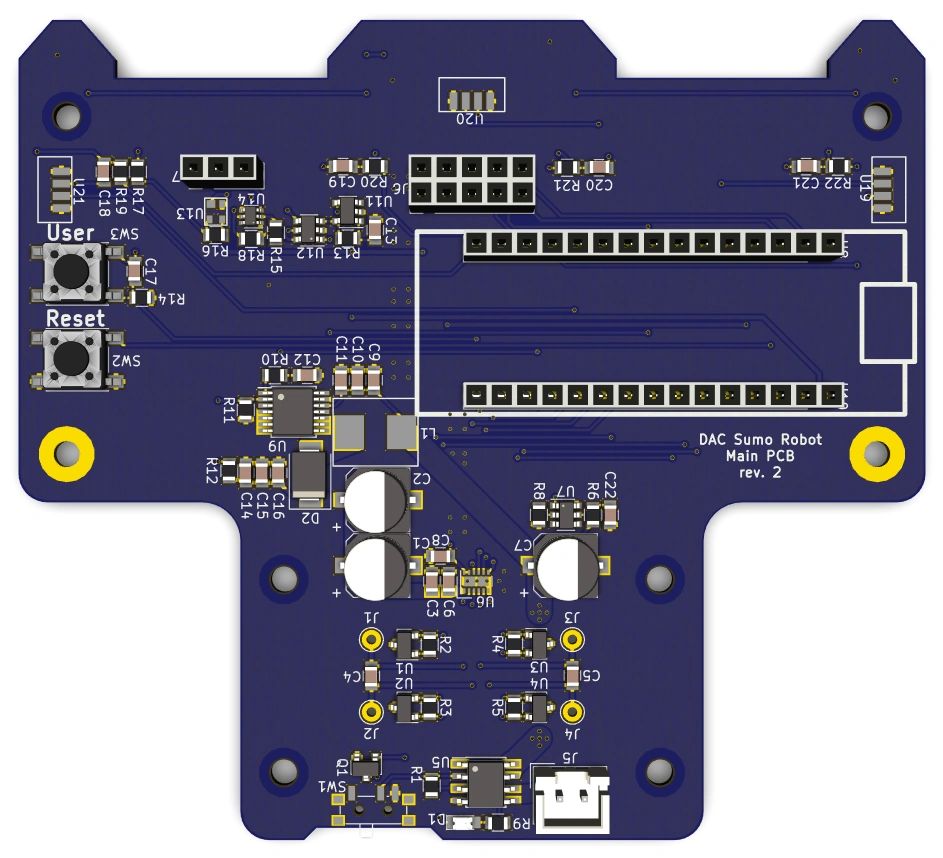
The photo shows the main board of McuMiniSumoRobot, an open project by Erich Styger and Simon Herzog (Lucerne University of Applied Sciences and Arts): the board is the robot's base, with the motors in printed holders.
Photo: Erich Styger, GitHub (MIT License)
Designing the mini sumo PCB in KiCad
Your own board replaces a nest of wires: less weight, fewer joints to break. Design it in the free KiCad. The third diagram shows its blocks:
- the battery, a 2S–3S LiPo (7.4–12.6 V);
- the switch, reverse-polarity protection and fuse;
- the 5 V and 3.3 V regulators;
- the microcontroller (MCU);
- the motor drivers (H-bridges), fed straight from the battery;
- the motors;
- the opponent sensors — digital infrared and ToF (I2C);
- the line sensors (ADC);
- the start module: START to the controller, KILL to the drivers' enable pin, so Stop works even if the program hangs;
- the programming port, LEDs and a DIP switch;
- a capacitor at the drivers.
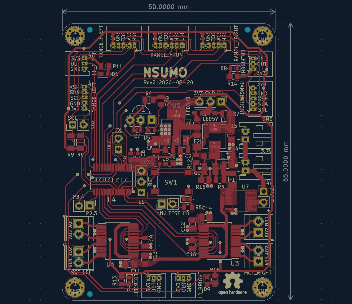
A good example is Nsumo by Niklas, a Swedish engineer (Artful Bytes): a two-layer 50 × 65 mm board, an MSP430G2553, two TB6612FNG drivers for four motors and a TSOP382 infrared receiver:
Layout rules: wide motor traces (on 35 µm copper, 3 A needs about 1.3–1.5 mm); capacitors at the driver; a solid ground plane; the infrared receiver on top; locking connectors.
The photo shows the Nsumo board layout in KiCad.
Photo: Artful Bytes, GitHub (MIT License)
Making the board: ordering, SMD soldering and bring-up
- Files. Run the design rule check (DRC), then export Gerber and drill files, the bill of materials (BOM) and placement file.
- Ordering. A two-layer FR-4 board, 1.6 mm thick, is a standard product at any PCB fab. To reflow the surface-mount (SMD) parts, order a metal stencil too.
- Hand soldering. 0805 and 0603 parts: a fine tip, flux and tweezers; tin one pad, tack the part, solder the other side. A fine-pitch chip (TSSOP) is drag-soldered with flux; bridges come off with copper braid (wick).
- Reflow. Spread solder paste through the stencil, place the parts and heat the board on a hot plate or in an oven following the paste's profile (the peak is about 220 °C for leaded paste, 245 °C for lead-free). Inspect every pin under a magnifier.
- Bring-up. Motors unplugged, check power and ground for shorts; power up from a bench supply limited to 100–200 mA; measure 5 V and 3.3 V; flash a blinking-LED program; then test the sensors, the start module and, last, the motors.
Safety: extract soldering fumes and wash your hands after leaded solder.
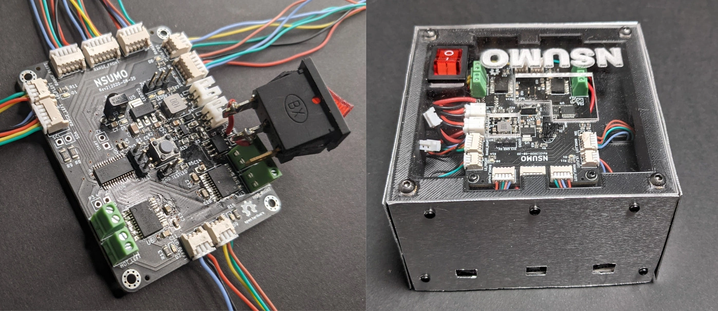
The photo shows the assembled Nsumo board and robot.
Photo: Artful Bytes, GitHub (MIT License)
Mechanics: CNC machining, laser cutting, 3D printing and the blade
- CNC machining — the frame, blade base and motor mounts in aluminium (6061, or the stronger 7075). The machine cuts a motor pocket to a tenth of a millimetre. An inside corner can be no sharper than the cutter's radius; deburr every edge.
- Laser cutting — flat parts: a CO2 laser cuts acrylic and plywood, a fibre laser sheet steel, so blade blanks are often ordered from a laser-cutting shop. Allow for a kerf of about 0.1–0.2 mm. Styger's laser-cut outline is an SVG file in his project.
- 3D printing — prototypes, brackets, wheel hubs and tyre moulds; more in 3D printing a robot.
The blade is the most "pro" part of a mini sumo:
- Material: a thin strip of hardened spring or tool steel on a rigid base. Drill the holes before hardening, or cut them by laser or spark erosion (EDM).
- Grind the edge straight across its whole width on a surface grinder or a diamond plate. An edge overheated until it turns blue has lost its hardness.
- Deburr: a burr scratches the ring's paint, and at RoboChallenge a scratch beyond about 5 cm × 2 mm is a major violation.
- Set the height with shims: on a flat plate, with a light behind, no light may show under the edge.
- The blade must not be white, and off the ring it wears a cover.
Safety: glasses and a closed door at the CNC machine, no gloves near the cutter; never laser-cut PVC (it gives off chlorine gas); when grinding, keep sparks away from anything flammable and hold small parts in a vice.
Tyres: casting silicone and polyurethane
Push depends on grip, and grip on the tyre, so strong teams cast their own from soft polyurethane or silicone:
- The hub: print or machine it, with grooves so the rubber locks on.
- The mould: Erich Styger 3D-printed his (TireMold.stl is in his project); Dave Hylands turned his from UHMW plastic, with an acrylic lid and ejector screws.
- Release agent: Styger's first tyre stuck; with glycerine the second came out clean.
- Mix and pour: weigh the parts exactly (Styger's Shore A 20 polyurethane mixed 1 : 2 by weight, Hylands' 1 : 1), stir and pour slowly so the air escapes.
- Cure per the datasheet (Styger's took 16 hours), then trim the flash and true the tyre on its motor with sandpaper.
- Check: the tyre must not hold an A4 sheet for more than 2 seconds.
Softer rubber grips better but wears faster.
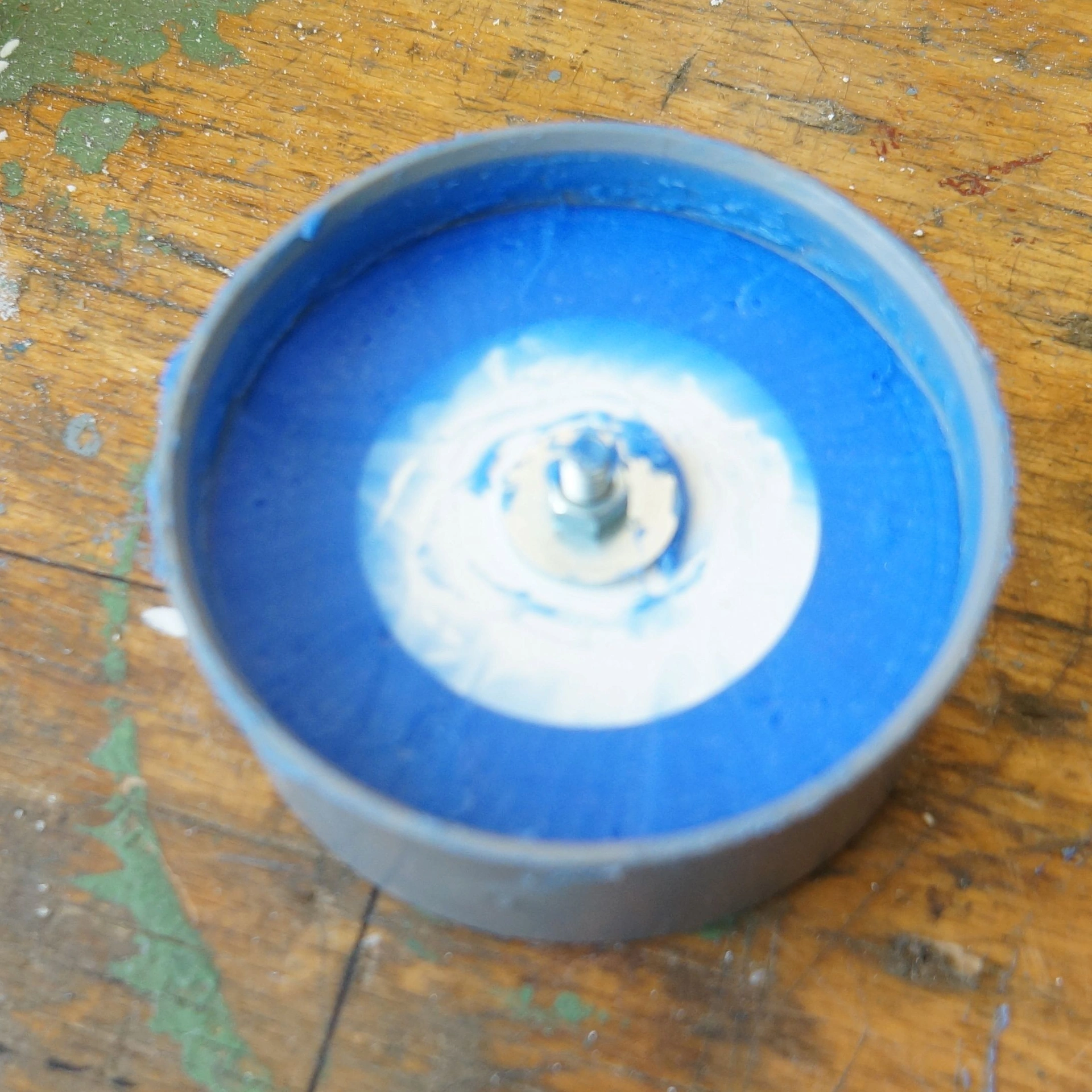
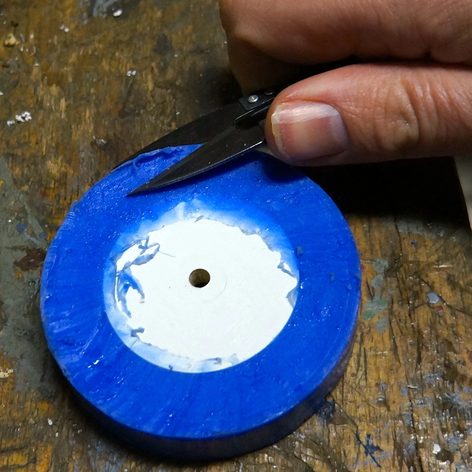
The photos show kenyer's simpler method for his mini sumo: a PVC pipe cap as the mould, filled with silicone sealant mixed 1 : 1 by volume with corn starch, which set in four hours; then the tyre is trimmed.
Safety: polyurethane contains isocyanates — gloves, glasses and ventilation; silicone sealant often gives off acetic acid vapour as it cures.
Photos: kenyer, Instructables (CC BY-NC-SA 4.0)
Motors, sensors and the start module
Motors. Mini Sumo mostly uses two or four metal micro gear motors, 10 × 12 mm in section (N20 size). Nsumo has four 6 V, 400 rpm motors: on a 30 mm wheel that is about 0.63 m/s. Choose the driver by the stall current: a TB6612FNG handles 1.2 A average and 3.2 A peak per channel. A bolder path is brushless: the OPRobots team's UltiBot drives two gimbal motors with FOC control.
Opponent sensors. A digital infrared sensor (JS40F type) answers "there" or "not there" fast, so it goes in front. A ToF sensor (VL53L0X, VL53L1X) measures distance but needs tens of milliseconds per reading, so it suits the sides. Nsumo carries five VL53L0X; they share one I2C address, so each needs its own XSHUT line.
Line sensors (QRE1113, for example) sit behind the blade edge at the corners, close to the ring.
The start module, under RoboChallenge's regulation, has four pins — VCC, GND, Start and Kill — and runs on 5 V or 3.3 V. Kill reads 1 at power-on and drops to 0 on the referee's Stop: that is the pin to wire to the drivers' enable. Mount the module on top.
Assembling the mini sumo, step by step
- Mechanics first, without electronics; check the size in a home-made 102 mm frame.
- Motors: shafts parallel, all four wheels touching the table at once.
- Wheels: hub fixed with a set screw or glue; true the tyre last, on its motor.
- Blade: fix it and do the light test.
- Board: only a board that passed bring-up; motor leads short and twisted.
- Sensors in their places, wires secured with hot glue or Kapton tape.
- Battery low and snug; the switch within reach.
- Ballast low and screwed in, up to 490–495 g.
- Final check: frame, weight, start module, blade cover.
Programming: the strategy in plain words
The basic logic is in the step-by-step guide. Split a competition robot's code into two layers: drivers (motor PWM, line-sensor ADC, ToF I2C, the start module) and logic that only calls the drivers. That is how Nsumo's program is built, with this state machine:
- Wait — until the start signal;
- Search — spin on the spot or drive forward, alternating on a timer;
- Attack — left, straight or right, depending on which sensor sees the opponent;
- Retreat — the move depends on which line sensor saw white;
- Manual — remote control, for testing only.
Niklas tested it in his own 2D simulator before the ring. Tips:
- time with a millisecond counter, not delay();
- attack only after two or three detections in a row;
- pick between several openings (side-step, arc, straight charge) with a DIP switch between rounds. At RoboChallenge the robot moves the instant the signal arrives.
Testing, tuning and the homologation checklist
The basic tests are in the step-by-step guide. A competition robot also needs:
- A push test against a luggage scale on a wall: on good tyres the force nears the robot's weight.
- A heat test: after a ten-second shove, are the driver and motors too hot? Limit the current.
- A sensor test against a low, black, matt "opponent" under bright light.
- Sparring with a real robot, filmed and watched in slow motion.
The full homologation checklist is in the Mini Sumo article; run through it at home before an event: the 10.2 cm frame, the scale, the A4 sheet and the start module with a test remote.
LiPo battery: a balance charger, a fireproof bag, never unattended; retire a swollen pack; with children, an adult does the charging.
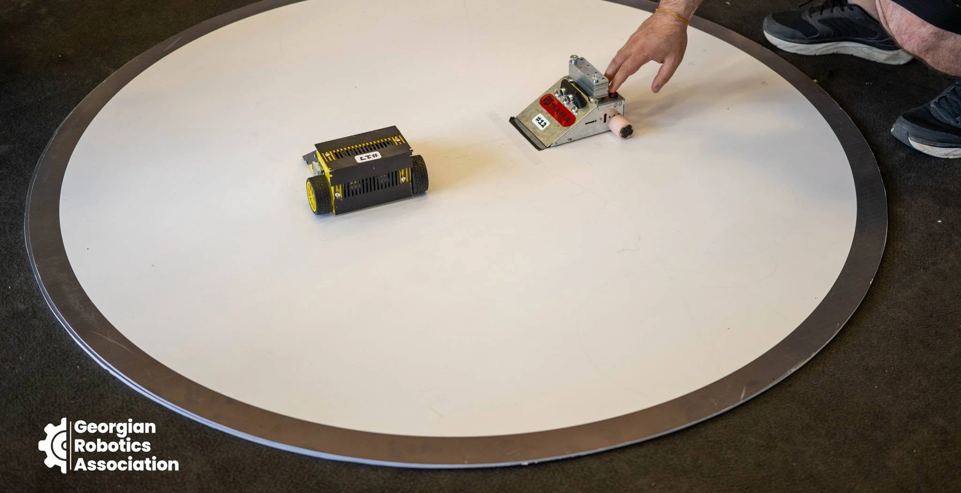
Mini and Micro Sumo fights at RoboChallenge 2025:
Other categories: how to build them
- Mega sumo robot build — 3 kg, 20 × 20 cm, the steel ring.
- Micro sumo robot build — 100 g in a 5 cm cube, the PCB as the body.
- Nano sumo robot — 25 g in 2.5 cm: miniaturisation at its limit.
- A competition line follower from scratch — a sensor-bar PCB, encoders and a Turbo-class fan.
- For beginners: how to build a sumo robot and a line follower step by step.
- Rules and champions: Mega Sumo, Mini Sumo, line follower.
- Combat robots: your first combat robot.
Getting ready to compete? GRA's championships and their rules are on the competitions page; for combat robots, registration for the international ROBO BATTLE 2026–2027 is open. All our articles on this topic: the sumo tag.
Sources and videos
- McuMiniSumoRobot, Erich Styger and Simon Herzog / GitHub
- New Concept for 2018 Mini Sumo Roboter, Erich Styger / MCU on Eclipse
- Making Perfect Sticky DIY Sumo Robot Tires, Erich Styger / MCU on Eclipse
- Nsumo hardware, Artful Bytes / GitHub
- Nsumo firmware, Artful Bytes / GitHub
- Grippy Robot Wheels, kenyer / Instructables
- Making Tires, Dave Hylands
- UltiBot, OPRobots / GitHub
- Mini Sumo regulation, RoboChallenge
- Mega Sumo regulation, RoboChallenge
- Micro Sumo regulation, RoboChallenge
- Nano Sumo regulation, RoboChallenge
- PCB Design Walkthrough Sumo Robot, Artful Bytes / YouTube
- Casting Urethane Tires for Mini Sumo Robotics, dtengineering / YouTube
- RoboChallenge Romania 2025 - Mini Sumo, Micro Sumo, SimeonBotics / YouTube
Photos: Erich Styger, GitHub (MIT License); Artful Bytes, GitHub (MIT License); kenyer, Instructables (CC BY-NC-SA 4.0). Cover photo and diagrams: GRA.