En

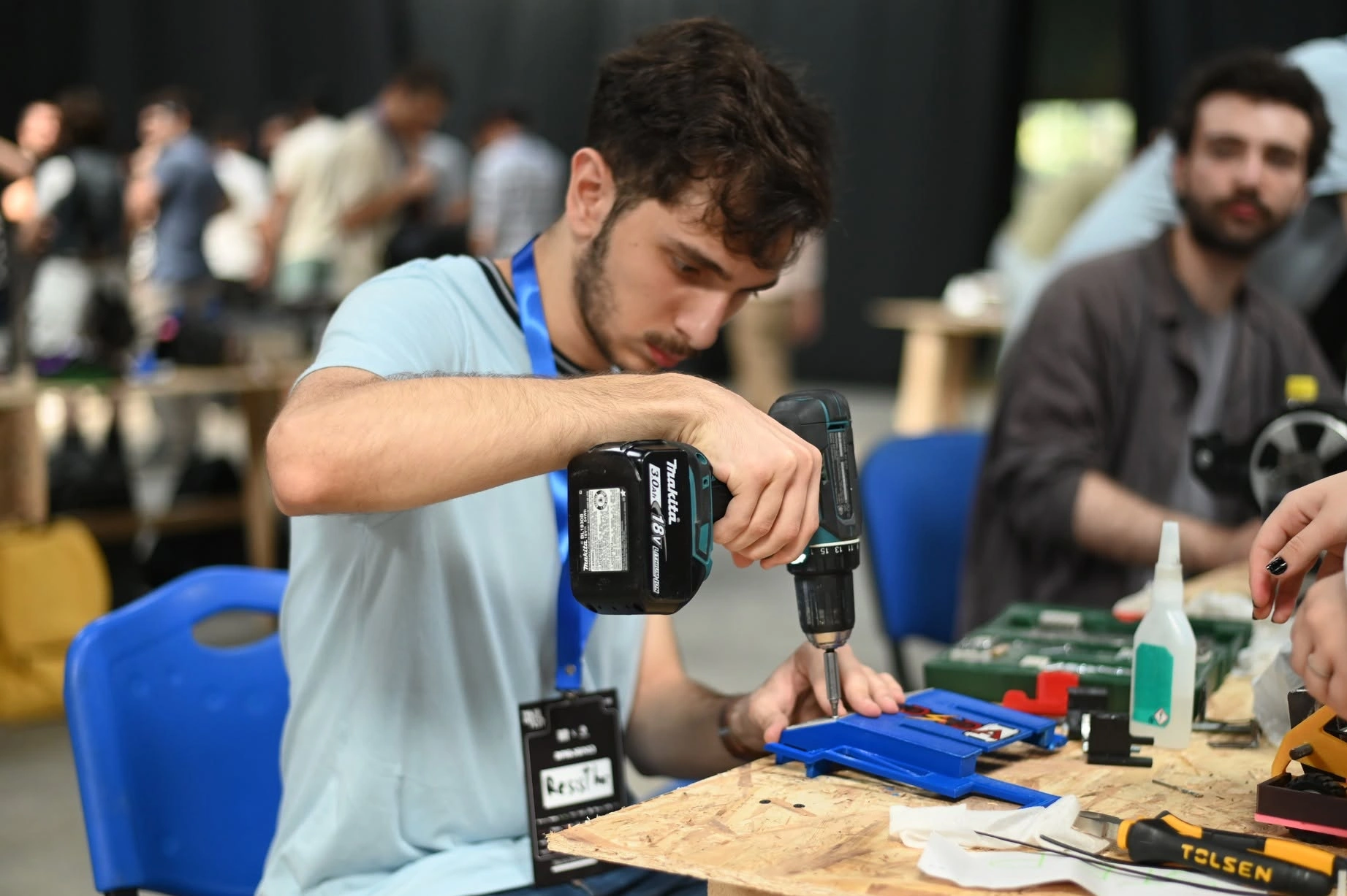
The racing line follower and the RoboChallenge classes
This article is a workshop: we build a racing line follower from scratch — a custom PCB, a light chassis, encoder motors and, for the Turbo class, a suction fan. New to line followers? Start with our beginner's build guide; PID, the rules and team Kavtazi are in a separate article. At RoboChallenge 2026 in Bucharest only 35 of the 83 robots in the classic class recorded a time (our results): reliability comes first.
Under RoboChallenge's 2026 regulations every class shares one frame: 25 × 25 cm and 1 kg, a black 15 mm line on white, curves of at least 75 mm radius, no angle sharper than 70°, no crossings, at most 3 minutes per run. Mapping the track is banned — if a robot does it, the track is changed.
- Line Follower (classic) — a suction fan (EDF) is allowed but not required.
- Turbo — the fan is mandatory and is tested at inspection with the robot upside down; the track has loops.
- Enhanced — a 10 cm gap in the line, a brick (about 25 × 12 × 6.5 cm) to drive around, and a seesaw.
- Advanced — new in 2026: the fan is mandatory, and the track climbs onto a ceiling, where the line is white on black and the robot runs upside down.
Each class adds a need: Turbo a fan and a sealed underside, Enhanced a distance sensor, Advanced suction stronger than the robot's weight. In the video, Mexico's Exotic Team races EVA-R in Turbo (2024); their NEON 01 won both classic and Turbo in Bucharest in 2026.
Designing a competition line follower: layout, weight, size
The first diagram shows the robot from above, roughly to scale:
- the curved sensor bar (the red sensors are over the line);
- the neck between the sensors and the main board;
- the microcontroller;
- motor drivers;
- gearmotors with encoders;
- wheels with silicone tyres;
- the suction fan and its sealed chamber (dashed);
- the LiPo battery;
- display, buttons, start receiver;
- skids or ball casters.
The dashed square is the 25 × 25 cm frame; d is the distance from the axle to the sensors.
- The board is the chassis: taifur's robot is one T-shaped PCB; OPRobots' DragonBot and FujitoraBot only add motor and fan mounts to theirs.
- Light: 1 kg is allowed, but Suckbot, described on Pololu's blog, weighed about 300 g with its battery; every gram costs acceleration and braking.
- Mass near the axle (as midhun_s does it) means less inertia in turns.
- An arc keeps every sensor about equally far from the axle; make it wide enough not to lose the line in a 70° corner.
- CAD first: the board in KiCad, the mechanics in FreeCAD, Fusion 360 or Tinkercad; check the fit with KiCad's STEP export and keep a weight budget.
Electronics: the schematic in blocks, and the sensor bar
In the second diagram red is power, black is signals, dashed is on/off control:
- LiPo battery, 2S–3S;
- switch and fuse;
- regulators, 5 V and 3.3 V;
- the microcontroller (MCU);
- the sensor bar with multiplexers (MUX);
- motor drivers;
- motors with encoders sending pulses (A/B) back;
- the ESC and the fan;
- a gyro;
- display, buttons, Bluetooth, start receiver;
- a voltage divider to measure the battery.
The controller: 32-bit, with plenty of ADC inputs and timers, fast enough for a 1 kHz control loop — STM32F103 (taifur), STM32F405 (FujitoraBot2), Teensy 3.6 (midhun_s), ESP32-C3 (PX-01, OPRobots' open modular kit).
Sensors: 12 (taifur), 16 (FujitoraBot), 24 through three 8-channel multiplexers (FujitoraBot2). Keep the pitch below the line width: on midhun_s's QTRX array, with an 8 mm pitch, two sensors always see the 15 mm line, so its position can be computed precisely. Cancel ambient light by reading each sensor with its emitter on and off and subtracting; a printed cover (taifur) helps too. Set the height by the datasheet: Pololu gives about 5 mm for QTR and 10 mm for QTRX.
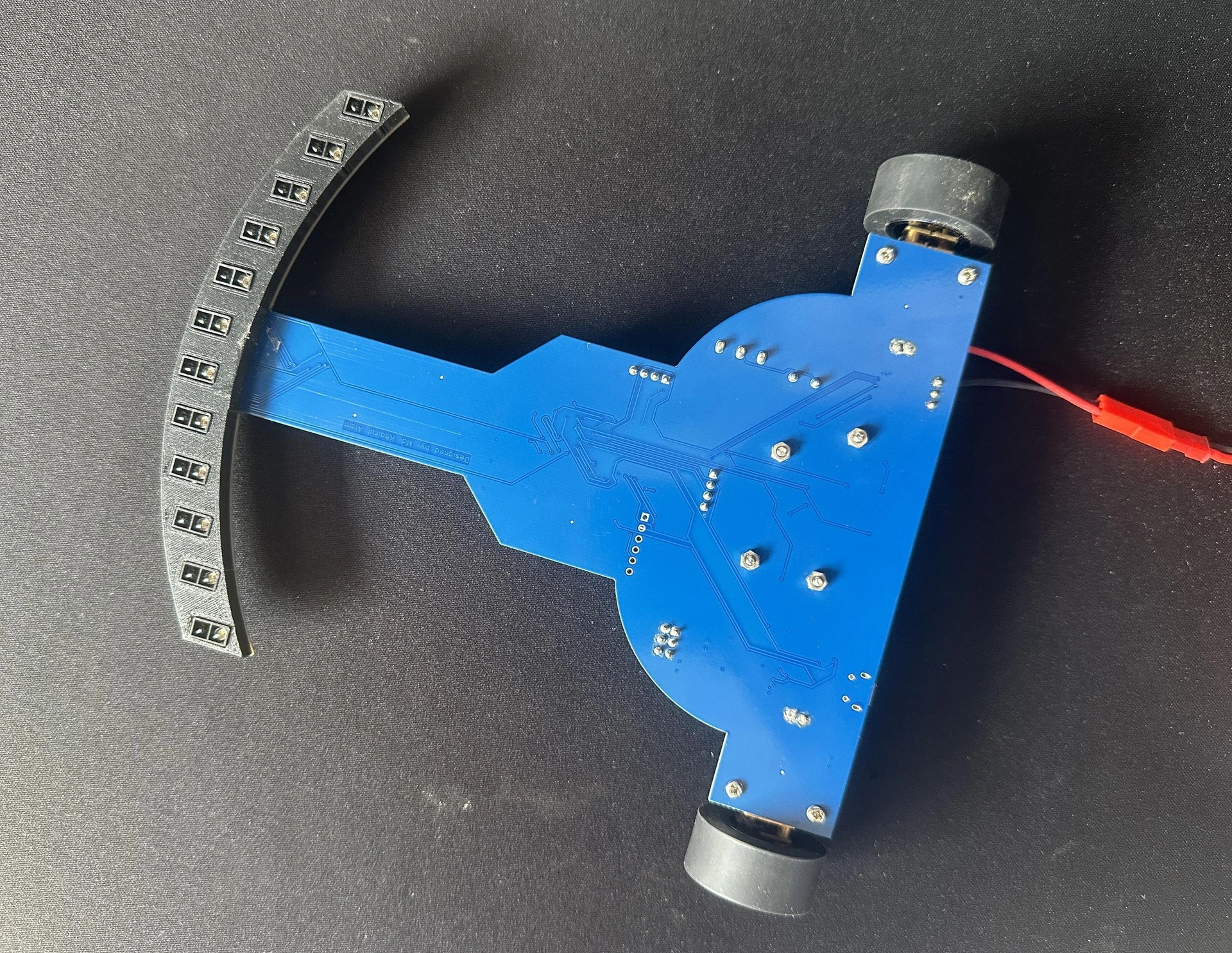
Size the drivers for stall current: a DRV8838 per motor (taifur), a TB6612FNG (DragonBot), paralleled DRV8833 channels (midhun_s). Use separate regulators for logic and sensors, and scale the PWM to the battery voltage. The photo: taifur's robot from below.
Photo: taifur, Instructables (CC BY-NC-SA 4.0)
The line follower PCB: design and manufacture
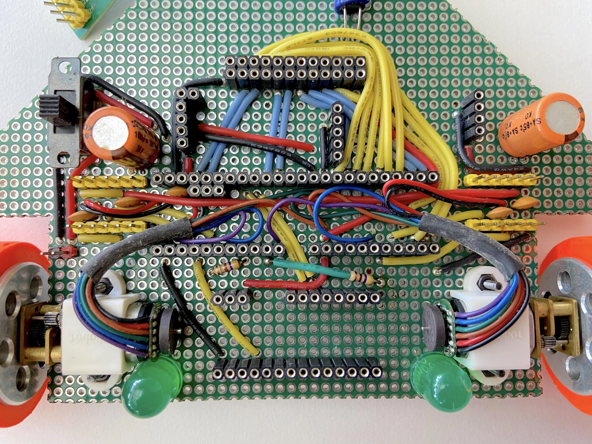
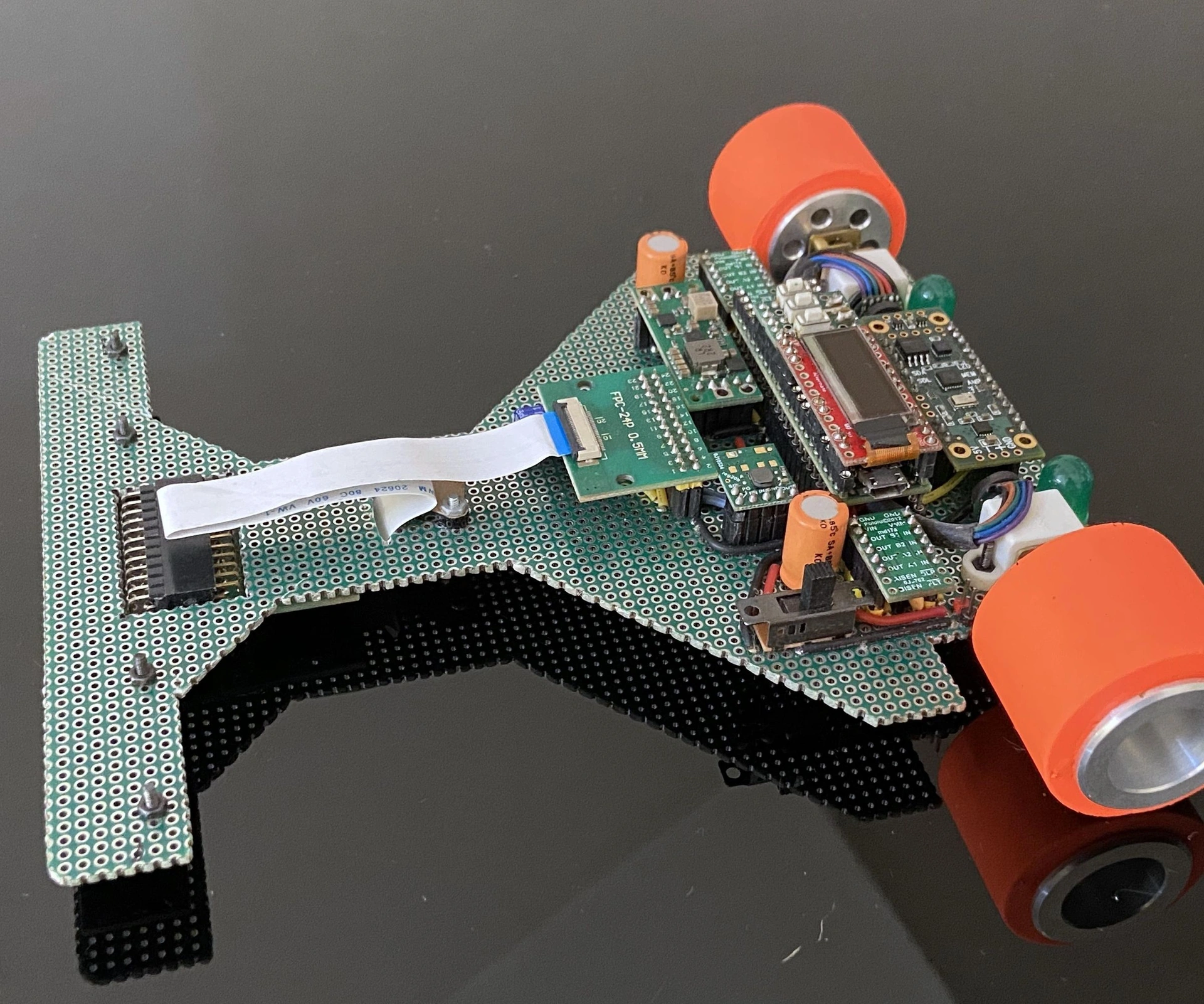
- Prototype first on perfboard — midhun_s's was also his robot's body.
- The schematic in KiCad (free; taifur used EasyEDA): a symbol and a footprint for every part; take the power circuits from the datasheets.
- Layout: wide motor traces, a full ground (GND) layer, a capacitor at every chip, sensor traces away from the motor PWM, an SWD programming header, test points. A sensor bar on a flat cable (midhun_s, PX-01) is easy to swap; PX-01's main board is two-layer and 1.2 mm thick.
- Check: DRC, the 3D view, a 1:1 paper print with the parts laid on it.
- Order: Gerber and drill files; a bare or an assembled board (PCBA) — the factory soldered taifur's SMD parts, and he added the motors, display and sensors.
- Soldering: a temperature-controlled iron, flux and tweezers, or a stencil, solder paste and a hot plate (reflow).
- First power-up: no short between supply and GND; power it first from a current-limited supply; check 3.3 V and 5 V; blink an LED; then the sensors, and the motors last, wheels in the air.
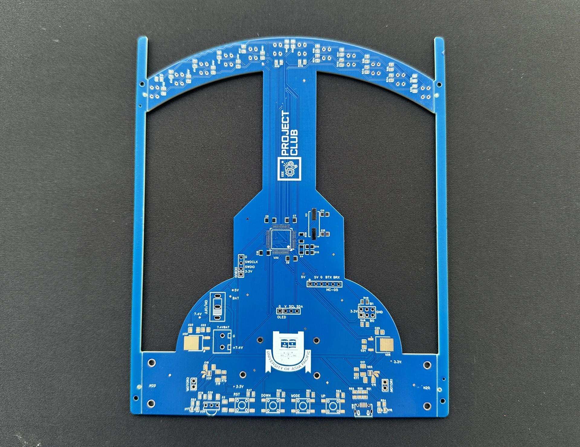
At home, etching (as the author of Black As Line did) or milling on a small CNC gives a simple single-sided board; fine-pitch chips need a factory board. Photos: taifur's board in its factory panel; midhun_s's prototype from below.
Photos: taifur and midhun_s, Instructables (CC BY-NC-SA 4.0)
Mechanics: 3D printing, CNC and laser cutting
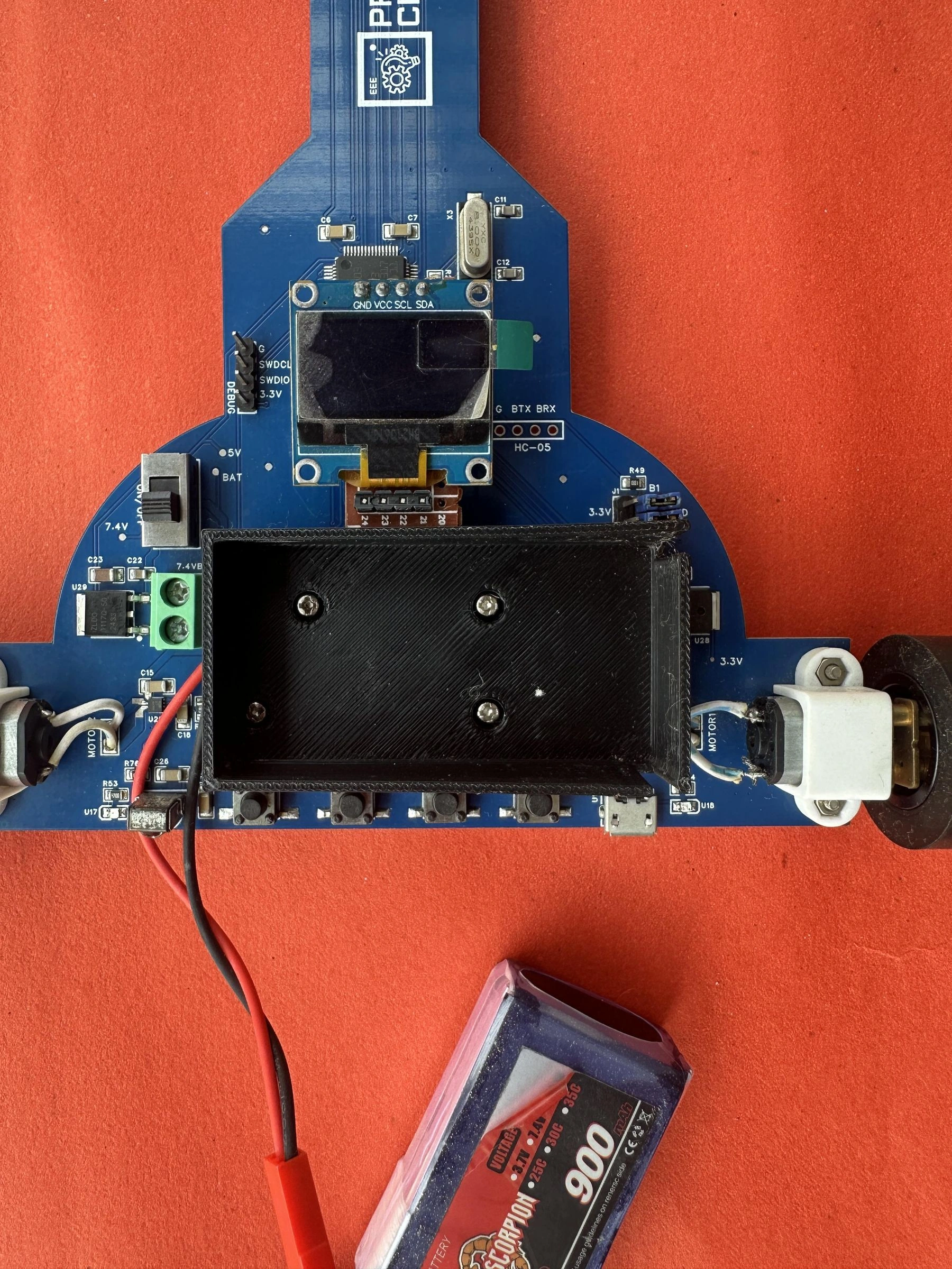
3D printing. taifur printed the sensor cover, the battery holder (photo), a two-ball caster and even wheels. DragonBot's mounts are PLA; FujitoraBot's are nylon PA12 made by selective laser sintering (SLS), stronger and more precise. Use PETG or nylon next to motors; print a test motor clamp first and adjust the hole in tenths of a millimetre (our 3D printing guide).
CNC machining. Mill the neck or the whole chassis from 1–2 mm carbon-fibre plate with a carbide cutter, keeping the dust down with water or a vacuum. Aluminium wheel hubs are turned on a lathe.
Laser cutting. Acrylic or plywood for prototypes and jigs, such as a 25 × 25 cm check frame. Never laser-cut carbon fibre, PCB material (FR-4) or PVC — they give off toxic fumes.
Photo: taifur, Instructables (CC BY-NC-SA 4.0)
Motors, encoders and wheels
The classic choice is an N20-size micro metal gearmotor in its high-power version: 10:1 gearing (taifur) is fast, 30:1 (Suckbot) pulls harder. Speed is v = π · D · n / 60 (numbers in our PID article).
Encoders need a motor with an extended back shaft. Pololu's magnetic encoder gives 12 counts per motor turn: at 10:1 that is 120 counts per wheel turn, about 0.8 mm per count on a 30 mm wheel. The line PID steers while a second loop holds the speed the encoders measure (FujitoraBot2), so the speed no longer sags as the battery drains. Encoders also give distance and position: midhun_s's robot computes its X–Y coordinates and heading.
Brushless motors are the top tier: FujitoraBot's two 1306-size 2700 kV motors run from a 4-in-1 BLHeli ESC. The ESC needs an arming sequence at power-up, and reverse has to be enabled in its settings.
Wheels: silicone tyres on aluminium hubs (midhun_s, photo), slot-car tyres (OPRobots), or printed wheels with silicone tubing stretched over them (taifur's tip). Casting tyres is covered in the Mini Sumo guide. Sticky tyres are banned (the A4 sheet test).
Photo: midhun_s, Instructables (CC BY-NC-SA 4.0)
The suction fan (EDF) for the Turbo class
A fan sucking air from under the robot adds downforce without adding mass. On the right of the third diagram, m·g is the weight, F the fan's force (6) and N the track's reaction. The cornering speed is roughly v ≤ √(μ · (g + F/m) · R): at R = 75 mm and μ = 1 it is 0.86 m/s without a fan, 1.21 m/s (41% more) with F equal to the weight, and 1.49 m/s with twice the weight; braking and acceleration improve too.
- EDF — a ducted propeller from model aircraft: PX-01 uses an EDF30 on a 20 A ESC; OPRobots advise up to 40% power in testing and 70% in competition, as it draws a lot of current.
- Centrifugal fan on a 1104-size 4000 kV brushless motor — about three times as efficient by OPRobots' figures, but home-made and less robust.
Suckbot's 30 mm fan (about 30,000 rpm) lifted only some 140 g on a 300 g robot — not enough to run upside down. Its lessons: keep the gap tiny (about 1.3 mm), and choose factory ball casters — the printed ones rolled badly under suction.
Spin the fan up before the robot moves: FujitoraBot2 starts it at half speed at 75% of the start countdown and stops it half a second after the run. For Advanced, F must clearly exceed the robot's weight.
Assembly, step by step
- The board: inspect it and solder what the factory did not fit.
- Encoders: the board on the motor's back, the magnet on the shaft; turn the wheel by hand and check that it counts correctly both ways.
- Motors: wheels parallel, square to the board, of equal diameter.
- Sensors: all at one height on their skids (check with a stack of paper).
- The fan: seal the chamber, set the gap, tie the wires clear of the blades.
- The battery near the axle, strapped down; the switch within reach.
- Weigh and measure: ≤ 1 kg and the 25 × 25 cm frame.
- Power-up with the wheels in the air: sensor readings, motor directions, encoder signs, and last the fan at low power, the robot held firmly.
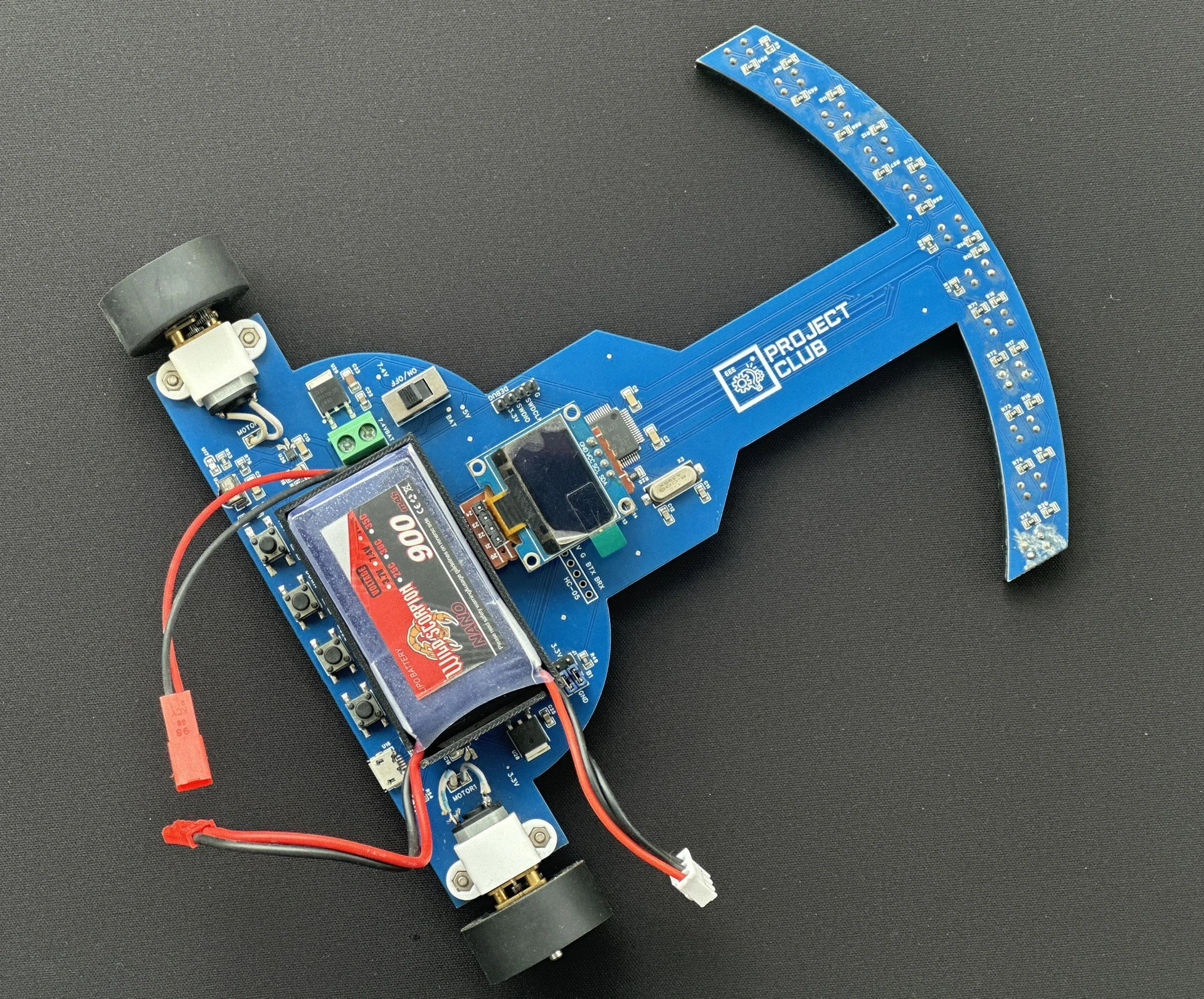
Photo and video: taifur's finished robot.
Photo: taifur, Instructables (CC BY-NC-SA 4.0)
Programming: speed profiles and track memory
The control loop runs on a timer at a fixed rate — 1,000 times a second on FujitoraBot2: sensors → line position → PD steering → encoder speed loop → PWM (PID theory).
Calibrate on the track: taifur's robot turns right, then left, storing each sensor's minimum and maximum; keep the values in EEPROM or flash.
Speed profiles: FujitoraBot2 has six, from 2 to 4.5 m/s, each with its own acceleration, braking and fan power; at 20 m/s² the robot reaches 4 m/s in 0.2 s. Start with a safe one.
Track memory (the third diagram, left): accelerate (1), brake (2), hold the speed the radius R allows (3), accelerate out (4). Braking must begin (v²max − v²R) / (2a) before the curve, so the robot must know in advance where the curve is. In Japan's Robotrace (a white line on black), markers beside the line (5) show where the curvature changes; robots record the course on a first lap with their encoders and gyro, then brake exactly in time — in the 2023 All Japan student contest hayabusa2.2 averaged 4.927 m/s this way, with suction fans. midhun_s's ACCL mode does it by hand: you enter the lap length and the fast stages by distance.
At RoboChallenge mapping is banned, so adapt the speed live: slow down when the line nears the edge of the bar or the gyro shows a fast turn, and speed up on long straights.
Enhanced and Advanced: cross the gap on gyro and encoders, drive around the brick when the distance sensor sees it, and invert the sensor readings on the ceiling. Telemetry: FujitoraBot2 logs up to 30,000 records per run, showing where the line was lost.
Testing, homologation and safety
A practice track to the rules: a matt white board, 15 mm black tape, 75 mm radius curves, 70° corners, lines 15 cm apart; a loop for Turbo; a gap, a brick and a seesaw for Enhanced. One change per run, log every time, and test with a half-empty battery and in different light.
Homologation (inspection): the bottomless 25 × 25 cm frame and ≤ 1 kg (checked again before every attempt); the A4 sheet (≤ 2 s); for Turbo, the fan test upside down; the organisers' number clearly visible; a start by button or infrared remote; a charged spare battery.
Safety:
- LiPo — a balance charger, a fireproof bag, never unattended; never below 3 V per cell; retire a swollen pack.
- Soldering and reflow — ventilation; wash your hands after leaded solder.
- Carbon-fibre dust — harmful and conductive: water or a vacuum, a respirator, glasses.
- Laser cutter — never unattended, an extinguisher close by.
- Fans spin at tens of thousands of rpm: hold the robot firmly, keep fingers clear, wear glasses, and unplug the battery when you work on it.
Other categories: how to build them
- Mega Sumo — 3 kg, 20 × 20 cm: a CNC-machined frame and 3D printing.
- Mini Sumo — 500 g, 10 × 10 cm: the PCB as chassis, SMD soldering, cast tyres.
- Micro Sumo — 100 g, 5 × 5 cm: miniaturisation, the PCB as the body.
- Nano Sumo — 25 g, a 2.5 cm cube: the smallest parts there are.
- For beginners: a SUMO robot step by step and a line follower step by step.
- Rules and champions: Mega Sumo, Mini Sumo, line follower, PID and Kavtazi.
- Combat robots: building your first combat robot.
Getting ready to compete? GRA's championships and their rules are on the competitions page; for combat robots, registration for the international ROBO BATTLE 2026–2027 is open. All our articles on this topic: the line follower tag.
Sources and videos
- Professional Line Follower V1, taifur / Instructables
- Advanced Line Following Robot, midhun_s / Instructables
- FujitoraBot, FujitoraBot2 and DragonBot, OPRobots / GitHub
- PX-01 OPRobots Linefollower KIT, OPRobots / PCBWay
- Nathan's line following robot: Suckbot, Pololu Blog
- Black As Line, TheSuperSewcio / Instructables
- Regulations: Line Follower, RoboChallenge, Turbo, Enhanced, Advanced
- Robotrace rules (2010), New Technology Foundation
- QTR Reflectance Sensors, Pololu and Magnetic Encoder Pair Kit, Pololu
- Videos: EVA-R at Robochallenge 2024, Exotic Team; PCB Line Follower - Part 1 of 2, Tech Recipe; hayabusa2.2, 2023 All Japan student robotrace contest, JUING-HUEI
Photos: taifur and midhun_s, Instructables (CC BY-NC-SA 4.0). Cover photo: Georgian Robotics Association, the pit area at ROBO BATTLE 2025.