En

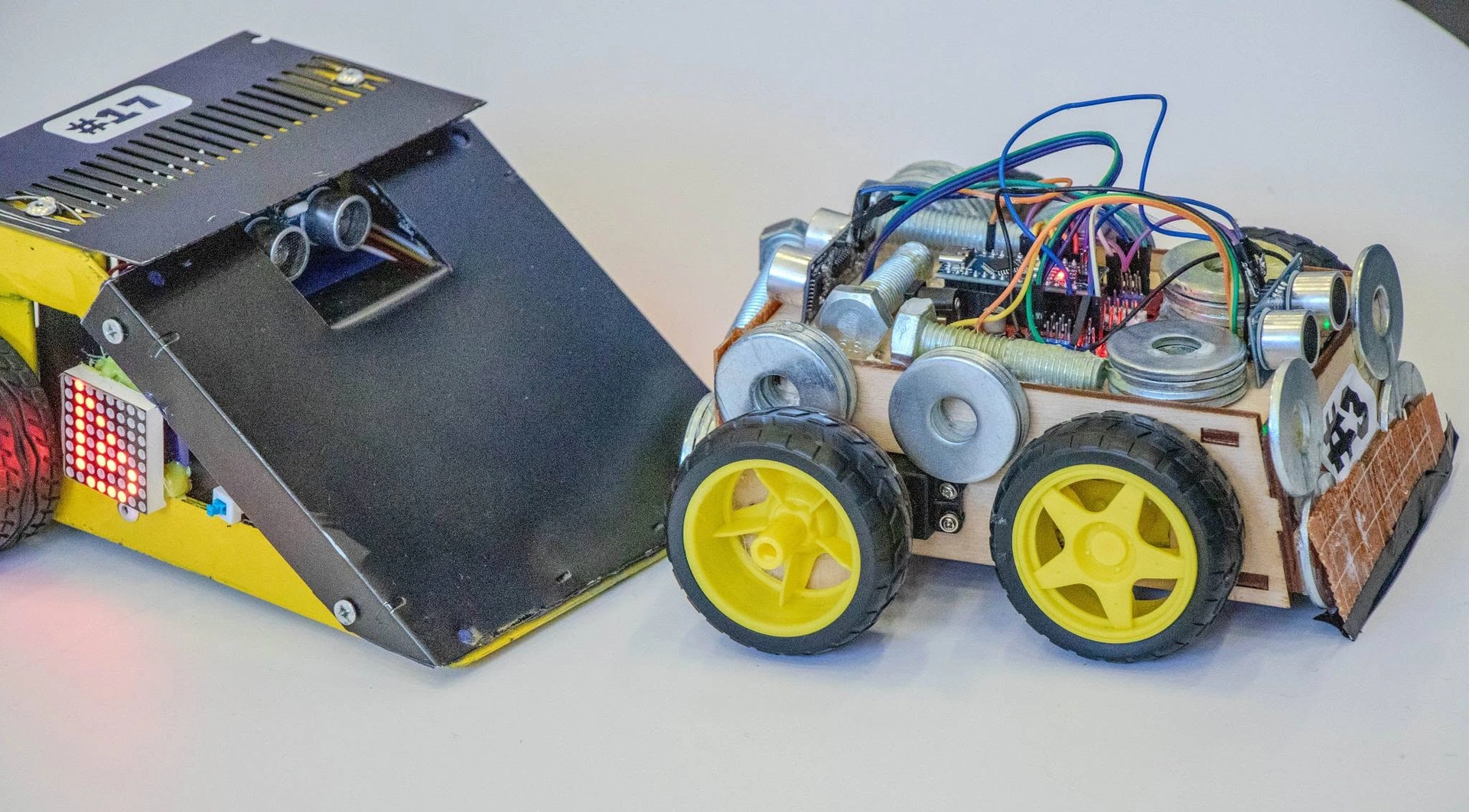
Mega sumo robot vs the other weight classes
Mega Sumo is the heaviest class of robot sumo: an autonomous robot that fits a 20 × 20 cm square and weighs under 3 kg. This guide shows how to build a mega sumo robot like experienced teams do: a CNC-machined frame, laser-cut armour, 3D-printed blocks, magnets and a PCB of your own. The rules and our champion RageByte are in Mega Sumo: rules and build tips, and RageByte's run in Bucharest is here.
Under the RoboChallenge 2026 regulations the classes differ in mass, size and ring (dohyo) — drawn to scale in the first diagram:
- Mega Sumo — 20 × 20 cm, any height, under 3 kg; a 154 cm black steel ring, 5 mm thick, with a 5 cm white border. Magnets and vacuum are allowed.
- Mini Sumo — 10 × 10 cm, under 500 g, 77 cm wooden ring (mini sumo build).
- Micro Sumo — 5 × 5 × 5 cm, under 100 g, 38.5 cm wooden ring (micro sumo build).
- Nano Sumo — a 2.5 cm cube, under 25 g, 19.25 cm wooden ring (nano sumo build).
The small classes ban downforce devices, and magnets don't work on wood. On steel they clamp the robot down with tens of kilograms of force, so in Mega everything is bigger — motors, gears, currents, frame loads. At GRA's 2026 championship Mega Sumo robots weighed 0.5–3 kg and a kill switch was mandatory.
Designing a mega sumo robot: CAD, size and weight budget
The main source of this guide is 3DP Sisaku H (2026), an open Instructables project by the Japanese builder noclaf8810373. The idea is simple: metal through-shafts tie two pairs of aluminium frames into a rigid box, so the printed blocks between them carry little load. The blocks hold the magnets, sensors and battery, and each swaps out alone — to test an idea you change one block, not the robot. Its predecessor, Sisaku-E (2023), was almost fully printed; in version H aluminium replaced the weak spots.
Design rules:
- Size margin: design slightly under 200 mm — a 203 × 203 mm bottomless frame checks the robot, and screw heads and wires bulge beyond the model.
- Weight budget: give parts their material in CAD so it computes the mass; list every part and weigh it once made. Fill the last grams with magnets — weight becomes grip.
- Low centre of gravity: magnets, battery and motors at the bottom.
- Fast service: rounds are a minute apart — reach the fuse and wheels without stripping the robot.
The second diagram shows how it is made: (1) the CAD model (the author works in Fusion 360); (2) CNC milling: STEP plus PDF drawing → frame; (3) laser cutting: DXF → armour; (4) 3D printing: STL/3MF → blocks; (5) PCB: KiCad → Gerbers; (6) dry fit; (7) magnets; (8) final assembly; (9) tests, whose lessons go back into CAD.
The author's video:
CNC machining and laser cutting: frame, armour, blade
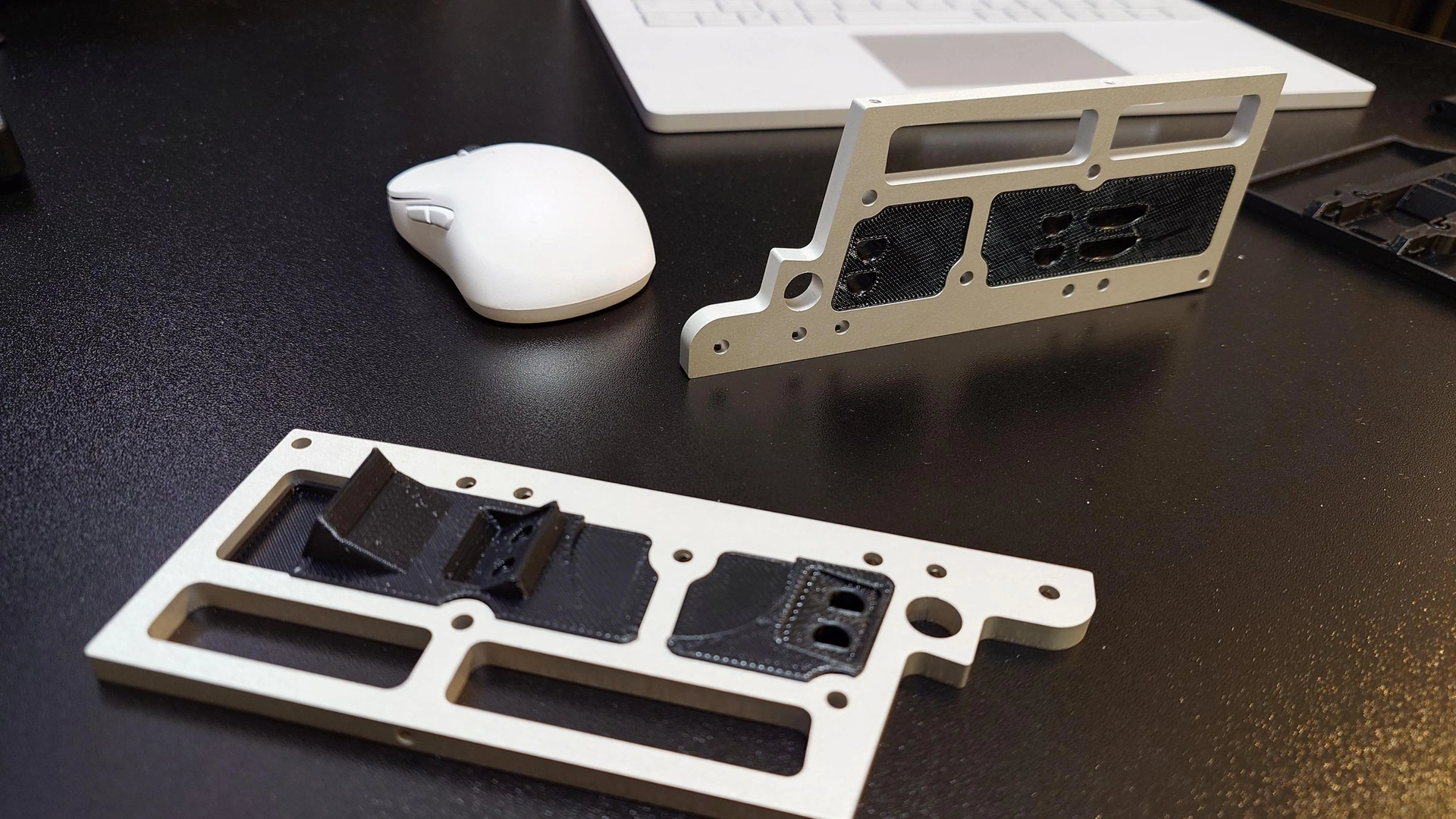
A CNC (computer numerical control) mill cuts metal straight from the 3D model to hundredths of a millimetre. In Sisaku H four side frames are machined from high-strength 7075 aluminium and the rear cover from 1 mm carbon fibre sheet (CFRP). Pictured: a frame and the printed sensor mounts glued to it.
No machine? Order the part from an online machining service, as the author does:
- Send a STEP model and a PDF drawing with threaded holes and tolerances.
- Bearing and shaft holes need an H7 fit; for the rest the author asks for ±0.05 mm.
- M3 threads appear in the model only as pilot holes — state that they must be tapped.
- If H7 is hard to get, order the holes slightly undersize and finish them with a 4.05 mm precision drill or a reamer.
Laser cutting makes flat parts faster: the Filipino maker aaronOS had a 1 kg sumo chassis cut from 2.2 mm aluminium sheet by sending DXF files to a laser-cutting shop.
Armour and blade. Sisaku H's three-piece front armour is laser-cut from thin sheet; tin snips and an angle grinder also work if you go slowly, so the sheet doesn't warp. On it sit 200 × 23 × 2 mm No.5 blades, common in Mega Sumo; used ones get their sharp edges dulled with a diamond file. The Brazilian student team FEG Robótica (UNESP) found the 28° angle of their bent steel blade too steep in fights. The blade must not be white and stays covered off the ring.
Photo: noclaf8810373, Instructables (CC BY-NC-SA 4.0)
3D printing the body blocks
Sisaku H prints about thirty parts: blade bases, rims, inner blocks, magnet and sensor holders, battery case, covers. The basics are in our 3D printing guide; for Mega Sumo:
- Material: ABS takes impacts best but warps without an enclosed printer; otherwise PETG. Avoid fibre-filled filament — it shatters on impact, the author warns.
- Settings: 0.4 mm nozzle, 0.2 mm layers, 30–80% infill, more around the blade.
- Accuracy: calibrate first — if the shaft holes in the blocks and the aluminium frame don't line up, nothing fits.
After printing:
- Remove supports and clean the magnet pockets with a file.
- Flatten the blade base so the blade touches the ring along its whole length.
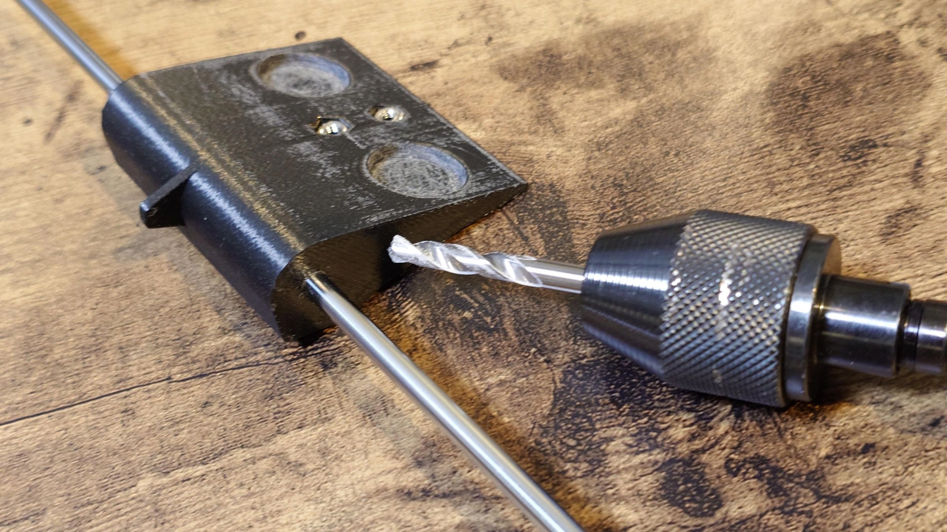
- Run a 4.05 mm drill through the 4 mm shaft holes (photo).
- Pull M2.6 nuts into their pockets with a screw, fix them with hot glue, remove the screw.
- Test self-tapping holes with one screw first: too tight splits, too loose won't hold.
Ventilate when printing ABS.
Photo: noclaf8810373, Instructables (CC BY-NC-SA 4.0)
Motors, gears, tyres and magnets
Motors. Top robots often use expensive coreless motors, like the Maxon DCX35L in the author's early robot. His Mabuchi RZ-735VA build costs about a tenth as much, but that motor overheats with constant starts and stops: keep runs under a minute, carry spares. The Brazilian team paired a 775-size brushed motor with a 64:1 planetary gearbox for about 2.1 m/s.
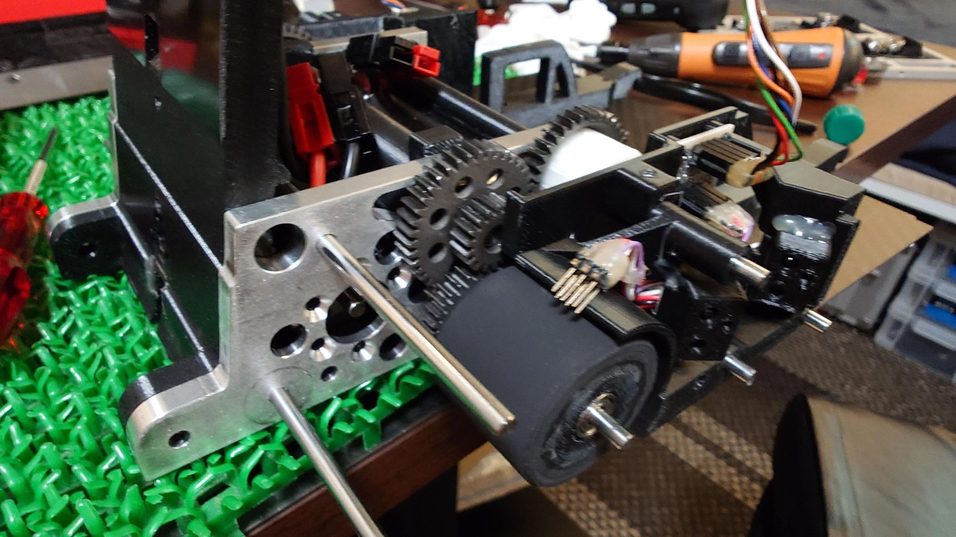
Gears. In Sisaku H a 14-tooth, module 0.8 pinion sits on the motor, a 38-tooth gear on the wheel rim and a double gear on a 6 mm shaft between them. To fix a gear on a shaft, degrease both, apply an anaerobic retaining compound and leave it unloaded until cured (about a day).
Tyres. Sisaku H's tyres are slices of rubber tube, super-glued to the rim and chamfered; bearings are pressed into the rim. The Brazilian team cast silicone tyres and measured motor current pushing a wall: on 50 Shore A tyres, 25 A without magnets, 40 A with them. Sticky tyres are banned (the A4 test).
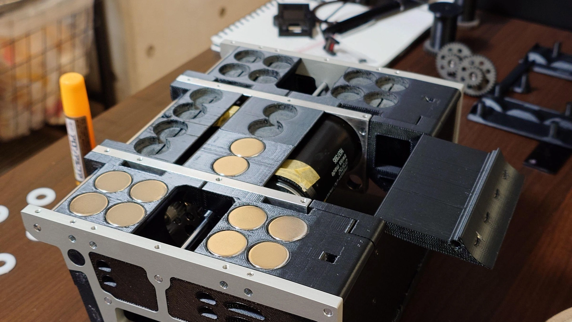
Magnets. Neodymium magnets pull the robot onto the steel. Sisaku H uses 20 magnets of Ø18 × 5 mm and 8 of Ø15 × 2 mm; the Brazilian robot had eight N45 magnets of Ø22 × 10 mm, about 10 kg of pull each, some 80 kg in all. The pull drops fast with distance: keep magnets close to the ring, not touching. Plan the polarity, too.
Gluing:
- First assemble the robot without glue and check everything — once the magnets are in, it won't come apart.
- Sand and clean both surfaces, glue the magnet in, fill gaps in thin layers.
- Cure 24 hours, scrape off excess glue, re-drill blocked holes.
Photos: noclaf8810373, Instructables (CC BY-NC-SA 4.0)
Electronics: designing and making the PCB
The third diagram shows the electronics: (1) LiPo battery; (2) fuse; (3) kill-switch relay, cutting motor power on Stop; (4) motor driver (two H-bridges); (5) motors; (6) DC-DC converter for the logic; (7, 8) two microcontrollers, linked by SPI in Sisaku H; (9) opponent and (10) edge sensors; (11) start/stop module; (12) 0–F tactic switch.
Sisaku H's control board is hand-wired on perfboard, with a separate driver on 14 and 16 AWG silicone wire; the Mabuchi version adds a 100 A driver and an 80 A fuse. The author calls his board a one-off and says you will have to design your own — which is where a PCB comes in. The Brazilian team used two boards so motor current would not upset the logic: one reads ten sensors, the other carries four BTN7970 half-bridges (two H-bridges), current sensing, TVS diodes and reverse-polarity protection.
Your own board:
- A block diagram like the one above.
- The schematic in the free KiCad, with a 100 nF capacitor at every chip's supply pin.
- Layout: power and logic apart, one ground point, short wide high-current tracks.
- Order: run the design-rule check (DRC), export Gerbers, order a two-layer board, or mill a prototype on a CNC.
- Solder: SMD by hand with flux, tweezers and a fine tip, or with paste, a stencil and a hot plate (reflow).
- Test: check for a short between battery plus and ground, power up first from a current-limited supply, then test power, sensors and motors (wheels in the air) one by one.
Electronics basics are here.
Sensors and the start/stop module
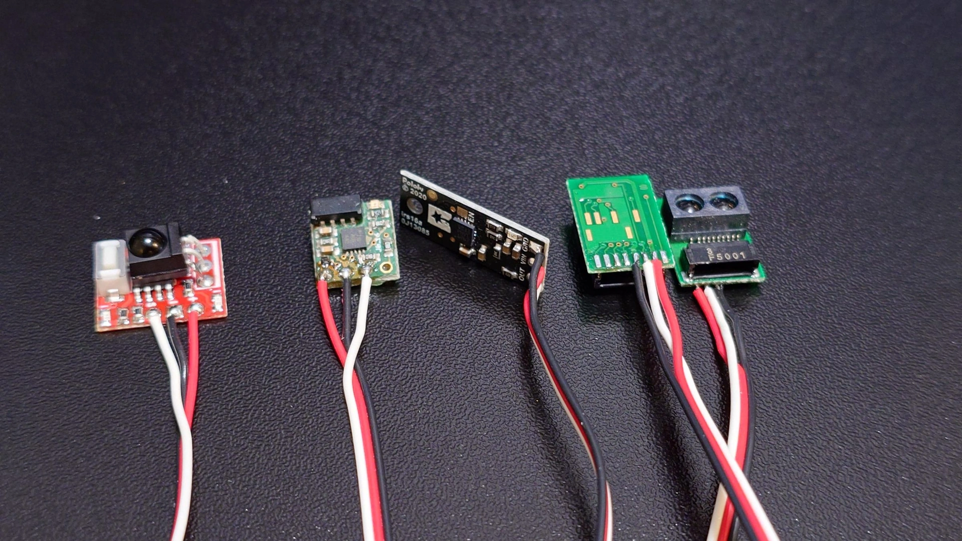
Sisaku H watches all around: a digital infrared distance sensor (IRS17A type) in front, GP2Y0E03 sensors and infrared detectors at the front corners, a detector on each rear side. There are four edge sensors: two in the blade bases, two at the back. Each gets a three-wire lead soldered on and is fixed with hot glue (photo): keep glue off the lens, leave slack along moving parts, test each sensor alone.
The Brazilian team swapped slow analog sensors (about 39 ms) for industrial laser ones: 0.5 ms response, up to 1 m, with an adjustable cut-off that ignores people beyond the ring. Sisaku-E showed at RoboChallenge 2023 that two robots' sensors can interfere — it weaved as it closed in on the opponent.
The start/stop module is mandatory at RoboChallenge: 3.3 or 5 V and four pins — VCC, GND, Start and Kill. Kill is high at power-up and drops to zero on Stop, driving a relay or optocoupler that cuts the driver's power. RoboChallenge recommends a kill switch; GRA's 2026 rules required it in the 3 kg class. Switch on 38 kHz sensors only after the start, so they don't confuse the start module's receiver. Details: our sumo build guide.
Photo: noclaf8810373, Instructables (CC BY-NC-SA 4.0)
Mega sumo robot assembly, step by step
Sisaku H's assembly order, in our words:
- Fix the gears on their shafts with retaining compound (one day).
- Press nuts into the printed parts; hinge the levers to the top covers on 3 mm shafts.
- Screw M3 × 4 set screws into the frames and inner blocks, finger-tight; glue the sensor mounts to the frames.
- Build the wheels and the two gear units on dummy rims (no tyre).
- Solder 16 AWG leads to the motors (red to plus, black to minus) and cover the joints with heat-shrink.
- Build the control unit and flash the firmware.
- Dry fit, armour on double-sided tape: check rigidity, gear mesh, sensor view, blade and cover movement, wiring.
- Glue in the magnets (24 hours), then mount the sensors.
- Final assembly: inner blocks, motors, shafts and bearings → gears → covers and blade bases → outer frames; lock the shafts with the set screws, fit the control unit, route the wires, tighten everything.
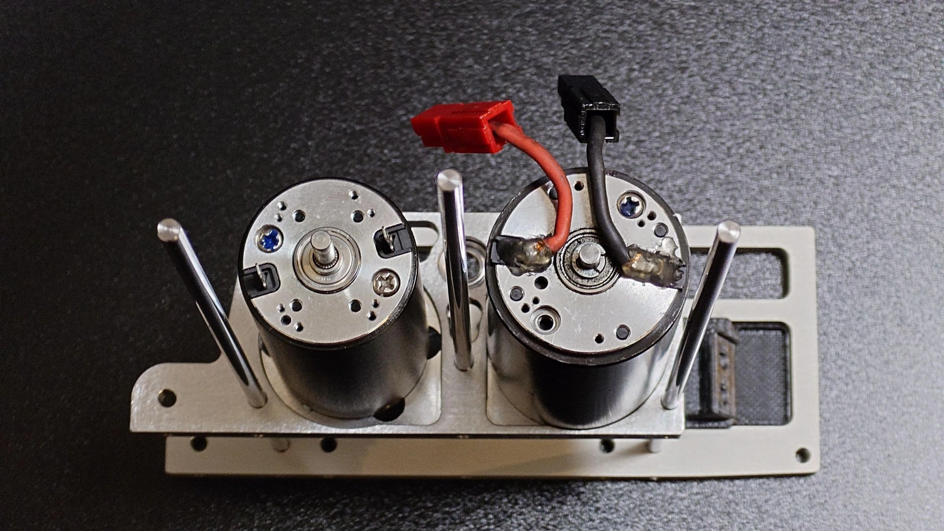
The photo shows the gear train. Many steps match the Mabuchi version, assembled on video:
Photo: noclaf8810373, Instructables (CC BY-NC-SA 4.0)
Programming, testing and homologation
The program is a state machine: wait → start → opening tactic → search → attack, with the edge sensors overriding everything (the basics). Sisaku H picks the opening tactic before the fight with a 16-position switch — that doesn't count as reprogramming.
Testing:
- Break-in: drive slowly forward, back and in circles for 10–20 minutes so the gears settle and motion becomes repeatable; only then calibrate straight runs and turns.
- Check each motor alone first, then the sensors and the start/stop.
- Practise on a steel sheet — magnets behave differently on wood.
- Check motor, driver and battery temperature after every run.
- Film your fights: an opponent drove over Sisaku-E, and the author concluded its front shape needed rework.
Homologation: the 203 × 203 mm frame; at most 3005 g with flags; working start/stop (and kill switch, under GRA's rules); the A4 test; a covered, non-white blade; the robot's number; gloves and safety glasses; spare fuses, charged batteries. Full list: our Mega Sumo article.
Workshop safety
- LiPo: a balance charger, a fireproof bag, never unattended; a short circuit means fire. Retire puffed packs.
- Soldering: a fume extractor or an open window.
- CNC machine: glasses, guards closed, no gloves or loose sleeves near the spinning tool; never clear chips by hand.
- Laser cutter: stay with it (fire), extraction on; never cut PVC — it releases chlorine gas.
- Grinder and blades: glasses and cut-resistant gloves; keep sparks away from batteries.
- Magnets: they pinch hard and shatter when they snap together; keep them away from electronics and pacemakers.
- Glues: ventilation and gloves.
- Testing: wheels in the air, kill switch in use, blade covered.
Other categories: how to build them
- Mini sumo robot build — 500 g: the PCB as the chassis, SMD soldering, cast tyres.
- Micro sumo robot — 100 g: tiny motors, the board as the body, a 1S LiPo.
- Nano sumo robot — 25 g: the smallest motors and controllers.
- Pro line follower build — a sensor-bar PCB, encoders, a fan for the Turbo class.
- For beginners: a sumo robot step by step, a line follower step by step.
- Rules and champions: Mega Sumo, Mini Sumo, line follower.
- Combat robots: your first combat robot.
Getting ready to compete? GRA's championships and their rules are on the competitions page; for combat robots, registration for the international ROBO BATTLE 2026–2027 is open. All our articles on this topic: the sumo tag.
Sources and videos
- 3DP Sisaku H: Modular, Durable Design With CNC Upgrades, noclaf8810373 / Instructables
- Mega Sumo Robot Autonomous Sisaku-E, noclaf8810373 / Instructables
- 3DP and CNC Mega Sumo Robot With Mabuchi Motors, noclaf8810373 / Instructables
- FFF 3D-Print Mega Sumo Robot, noclaf8810373 / Instructables
- 3 kg sumo robot hardware (Portuguese), Miranda Neto / UNESP, 2017
- 1KG Sumobot Build, aaronOS / Instructables
- Mega Sumo, RoboChallenge
- Mini Sumo, RoboChallenge
- Micro Sumo, RoboChallenge
- Nano Sumo, RoboChallenge
- Robot Start Module, p1r.se
- Video: Sisaku H, noclaf8810 / YouTube
- Video: Mabuchi Motors, noclaf8810 / YouTube
- Video: Robochallenge 2023, noclaf8810 / YouTube
Photos: noclaf8810373, Instructables (CC BY-NC-SA 4.0); cover: GRA, school sumo competition 2024.