En

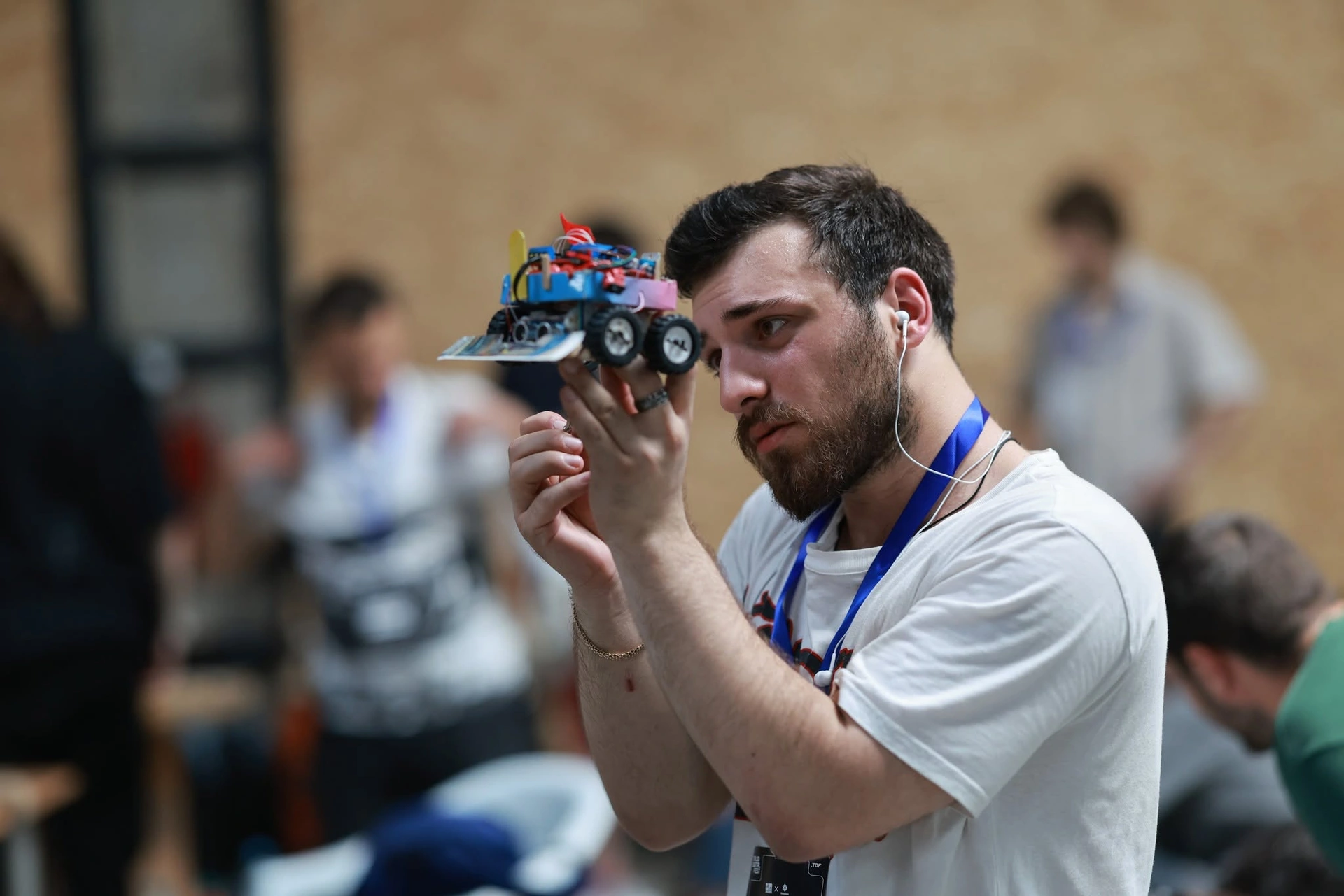
Nano sumo robot: the smallest sumo class
A nano sumo robot belongs to the smallest class of robot sumo: it must fit in a 2.5 cm cube and weigh under 25 grams, about as much as five sheets of office paper. It is fully autonomous, starts on the referee's infrared signal and pushes its opponent off a black ring only 19.25 cm across.
New to sumo? Read our step-by-step sumo robot guide and the Mini Sumo rules first. This is the workshop: how to build a nano sumo robot, from CAD and the circuit board to hand-made wheels and ring tests.
The class is alive: at RoboChallenge 2025 in Bucharest, HBFS Robotics of the University Politehnica of Bucharest took first and second place in Nano Sumo, and the Catalan builder Ferran Gascon won the nano class at Vienna's RobotChallenge (a different event) three years running, 2010–2012, with FuriousPuça. GRA's championships have no nano class yet (see our RoboChallenge 2026 results), so this guide serves teams heading abroad.
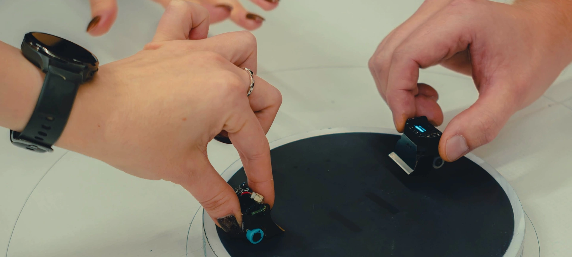
In the photos: a nano sumo match at RoboChallenge 2026 in Bucharest — the robot fits between two fingers. Photo: Ionescu Darius (LSE București).
Robot sumo weight classes: from Mega to Nano
Under RoboChallenge's current regulations (November 2026), mass and size set the class, and the ring scales with them:
- Mega Sumo — under 3 kg, 20 × 20 cm, any height; a steel ring Ø 154 cm with a 5 cm white border; magnets and vacuum allowed.
- Mini Sumo — under 500 g, 10 × 10 cm, any height; a wooden ring Ø 77 cm, 2.5 cm border.
- Micro Sumo — under 100 g, a 5 cm cube; ring Ø 38.5 cm, 1.25 cm border.
- Nano Sumo — under 25 g, a 2.5 cm cube; ring Ø 19.25 cm, 6.25 mm border.
Each step halves the robot's side and the ring's diameter. Fans and suction pumps that press a robot down are banned everywhere except Mega, and a robot that fits a smaller class may not enter Mini or Micro.
The first diagram shows the nano ring and robots to scale (left) and the inspection (right):
- the black wooden surface, 1.25 cm thick;
- the white border, 6.25 mm;
- the start lines (shikiri-sen), 25 × 10 mm;
- two 25 × 25 mm robots;
- homologation: a bottomless 26 × 26 mm frame, height under 26 mm;
- the scale: 26 g at most;
- the A4 test: tyres must not hold an 80 g/m² sheet for over 2 seconds;
- the referee's infrared remote and the robot's mandatory start/stop receiver.
With only 1 mm and 1 g of margin, design for 24–24.5 mm and about 24 g.
What is realistic for a school team
Nano is the hardest sumo class: build a Mini Sumo or a Micro Sumo first. Then choose a level:
- A hand-wired prototype. The Instructables author mikey77 built his Mr. Cube in one cubic inch from through-hole parts: two halves on pin headers, ready-made 6 mm gear motors and a chip mounted upside down. He warns that building this small takes about twice as long, and an inch (25.4 mm) is slightly over the limit.
- Your own circuit board. Grzegorz Piecuch, of the student robotics club at Rzeszów University of Technology, designed two double-sided boards for surface-mount (SMD) parts, and Patrick McCabe had his board made by a PCB service and reflow-soldered it. With a mentor, that is a realistic goal of a few months for a strong school team.
- Competition level. University teams such as HBFS refine their boards, sensors and code over years.
Tools: a magnifier, a fine-tip iron, 0.4 mm solder, flux, tweezers, a 0.01 g scale and a hot plate; a 3D printer, a laser cutter and a lathe at a makerspace or university.
The third diagram shows the process:
- the model in CAD;
- the board design, for example in KiCad;
- thin boards (0.8–1.0 mm) from a PCB service;
- solder paste, parts, then reflow;
- 3D printing: the body;
- laser cutting: flat parts;
- a lathe or CNC machine: wheels and axles;
- assembly;
- the checks. The red arrow is the next version: nano robots rarely work at the first attempt.
Design in CAD: millimetres and grams
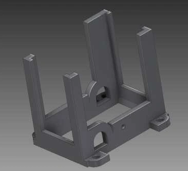
Piecuch first measured every part (motor, wheel, battery, sensor), modelled each one in CAD (he used Autodesk Inventor; FreeCAD or Fusion 360 will do), skipped details that did not matter, and only then designed the housing. In 25 grams, he notes, a designer has to rein in his imagination.
Weight and volume. The cube holds just 15.6 cm³, and mikey77 filled about 85% of his. Weigh every part on a 0.01 g scale and keep a table. A 6 mm GM15-type planetary gear motor weighs about 1.2 g according to its maker; a 25 × 25 mm fibreglass (FR4) board about 2 g at 1.6 mm thick, half that at 0.8 mm. Put the remaining mass low: push comes from grip, and grip from weight.
Physics. Maximum push is roughly μ·m·g: with μ ≈ 1, only 0.25 newtons for 25 g. Two such motors on 12 mm wheels give over 1 newton at stall on paper, so the wheels slip first: mass and tyres decide. Speed is the real problem: 920 rpm (3 V, the maker's figure) on a 12 mm wheel is about 0.58 m/s, a third of a second across the ring. With 25:1 gearing mikey77 found his robot too fast and jumpy, so plan for speed control early.
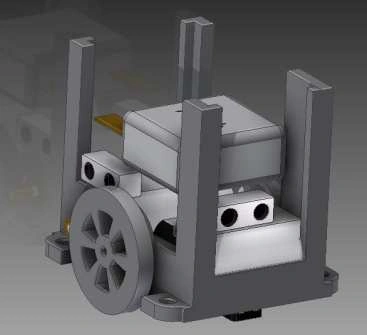
Pictured: Piecuch's virtual model and his housing designed for 3D printing.
Illustrations: Grzegorz Piecuch, JETACOMPS (CC BY-SA 4.0)
The PCB as the chassis: design and making
In nano sumo the printed circuit board (PCB) is often the robot's body. It carries the microcontroller (an Arduino Nano-sized board, 45 × 18 mm, will not fit; Piecuch used an ATmega8 and McCabe an ATmega328, both surface-mount chips), an H-bridge for two motors, the edge and opponent sensors, the start/stop module input, the LiPo with a switch and filter, an LED, a programming connector, and a battery-voltage input on an analog-to-digital converter (ADC) pin: Piecuch's robot shows its charge by how fast an LED blinks.
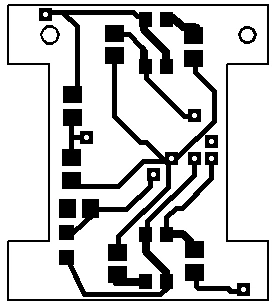
Piecuch could not fit everything even on one double-sided board, so he made two: the lower one is also the chassis (the picture shows its copper, H-shaped around the wheels), the upper one sits between the opponent sensors and the battery, and wires link them. McCabe's 21 × 23 mm board carries an ATmega328 with the Arduino bootloader, burned via ICSP, and an FTDI port; it plugs straight into a 1 A dual motor driver board.
In KiCad, import the outline from CAD (as DXF) with cut-outs for the wheels, place the fixed parts first (edge sensors at the front underneath, opponent sensors on the front edge), and keep motor traces short, wide and away from sensor lines: mikey77 found that motor noise confuses the inputs. Order a thin two-layer board with a stencil; then apply paste, place the parts with tweezers under a magnifier, reflow on a hot plate or with hot air (McCabe reflowed his board too), check for solder bridges and power up first from a current-limited supply.
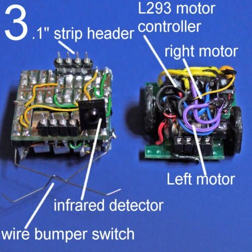
The photo shows the hand-wired way: mikey77 turned his L293 driver on its back ("dead bug" style), soldered thin wires onto its legs, coated it in liquid rubber and tucked it into a free gap.
Illustration: Grzegorz Piecuch, JETACOMPS (CC BY-SA 4.0)
Photo: mikey77, Instructables (CC BY-NC-SA 4.0)
Hand-made mechanics: motors, wheels and the body
For mikey77, the hardest part of a tiny robot is finding a small, slow gear motor. The builds give three answers:
- a 6 mm planetary-gear pager motor of the GM15 type: under 6 mm across, about 19 mm long, 25:1, 3 V, about 920 rpm at 100 mA; for McCabe's teammate Gary it was the only gearbox that fitted, and mikey77 chose it too;
- a motor from a model micro-servo, Piecuch's advice for the most torque in the least space;
- the layout: two 19 mm motors cannot sit end to end on one axis (38 mm > 25 mm), so Gary drove the wheels through belts and mikey77 offset his motors, one wheel ahead of the other.
Wheels. Gary turned aluminium wheels on a lathe, belt groove included, on 2.39 mm steel axles, with 12 mm rubber O-rings (1.5 mm cross-section) as tyres. mikey77 sanded plastic pulleys to size on the running motors and coated them in liquid rubber. Bill Weiler's one-inch Skoobot rolls on laser-cut styrene layers glued with silicone. Any tyre must pass the A4 test.
The body. Piecuch 3D-printed his housing with no part hanging in mid-air (see our 3D printing guide). Weiler printed his complex body but laser-cut flat motor mounts from 0.8 mm acetal (Delrin), then heated them and bent them to 90 degrees in a jig. The rule of thumb: print complex shapes, laser-cut flat parts, and turn precise round metal on a lathe or a CNC machine.
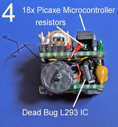
The photo shows the inside of mikey77's robot, labelled: motors, driver, infrared detector and bump "whiskers".
Photo: mikey77, Instructables (CC BY-NC-SA 4.0)
Sensors, the battery and the start module
Opponent sensors. Piecuch used infrared distance sensors with a 6 cm range, McCabe a single digital obstacle sensor, and Weiler a VL6180X-type time-of-flight (ToF) sensor reaching about 10 cm, nearly half the ring. Mount the sensor low and at the front.
Edge sensors. The Romanian builder Andrei Popescu-Filimon's QRE1113GR reflectance module for mini, micro and nano sumo is just 7.9 × 7.2 mm and works best 3 mm above the surface. The border is only 6.25 mm wide, so read it in every loop.
The battery. McCabe used one 50 mAh 20C LiPo cell (4.2 V when full, up to 1 A), and Piecuch's model shows a 70 mAh cell. mikey77's button cells ran flat within minutes, with the motors drawing 90–115 mA. Over-discharging kills a LiPo, so Piecuch's robot keeps measuring its voltage; McCabe even built a charger around a MAX1555 chip.
The start/stop module. It is mandatory at RoboChallenge: four pins (VCC, GND, Start, Kill), 5 or 3.3 V; the Start pin reads 0 at power-on, 1 on start and 0 on stop. The ready-made module in GRA's rules (10.5 × 12.5 × 4 mm) takes a fifth of the nano footprint, but RoboChallenge also accepts your own hardware: a 38 kHz infrared receiver decoded by your own microcontroller (RC-5 in GRA's rules, see our sumo robot guide; check with the organisers). A robot with a faulty module cannot compete.
Nano sumo robot assembly, step by step
The second diagram shows one typical nano sumo layout from the side, inside the 25 × 25 mm limit:
- the wedge (blade);
- an edge sensor, about 3 mm above the surface;
- the lower board, which is the chassis;
- a 6 mm motor, lying lengthwise;
- a 12 mm wheel with an O-ring tyre;
- the LiPo cell;
- the upper board with the microcontroller;
- an opponent sensor;
- the start/stop receiver.
The assembly order:
- Test each board alone first; mikey77 breadboards a circuit before soldering and mounting it.
- Motors: at low speed both must turn the right way.
- The wheels must spin freely; mikey77's robot rests at the back on a nylon screw head, about 0.8 mm off the floor.
- Edge sensors at 3 mm; note the readings on black and white.
- The battery low and central; the switch within reach.
- The upper board on pin headers, removable for repairs; motor wires away from sensor wires.
- Sensors at the front, the receiver on top; the wedge touching the ring, and not white.
- Glue soldered wires down; finally, weigh the robot and pass it through the frame.
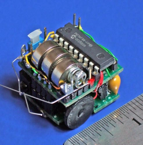
The photo shows mikey77's finished one-inch robot next to a ruler.
Photo: mikey77, Instructables (CC BY-NC-SA 4.0)
Programming for a 19 cm ring
The logic is the same as in bigger sumo, a state machine: wait, search, attack, escape the edge and stop (see our sumo robot guide). In nano, speed and space matter most:
- Read the start/stop pin first in every loop: 0 means the motors go off.
- Limit the speed. McCabe's program pulses the motors a few milliseconds at a time while searching, and mikey77 used pulse-width modulation (PWM) at about 30% of full speed. Keep full power for the attack.
- The edge. McCabe's code compares an analog sensor reading with a threshold: on white the robot backs up and turns.
- Priorities. Piecuch's robot keeps pushing an opponent it sees even at the edge, because when both robots fall, the one that left first loses. That is risky: do it only when the opponent is straight ahead.
- Calibrate the thresholds on a real ring and avoid long delays: the robot crosses the whole ring in a third of a second.
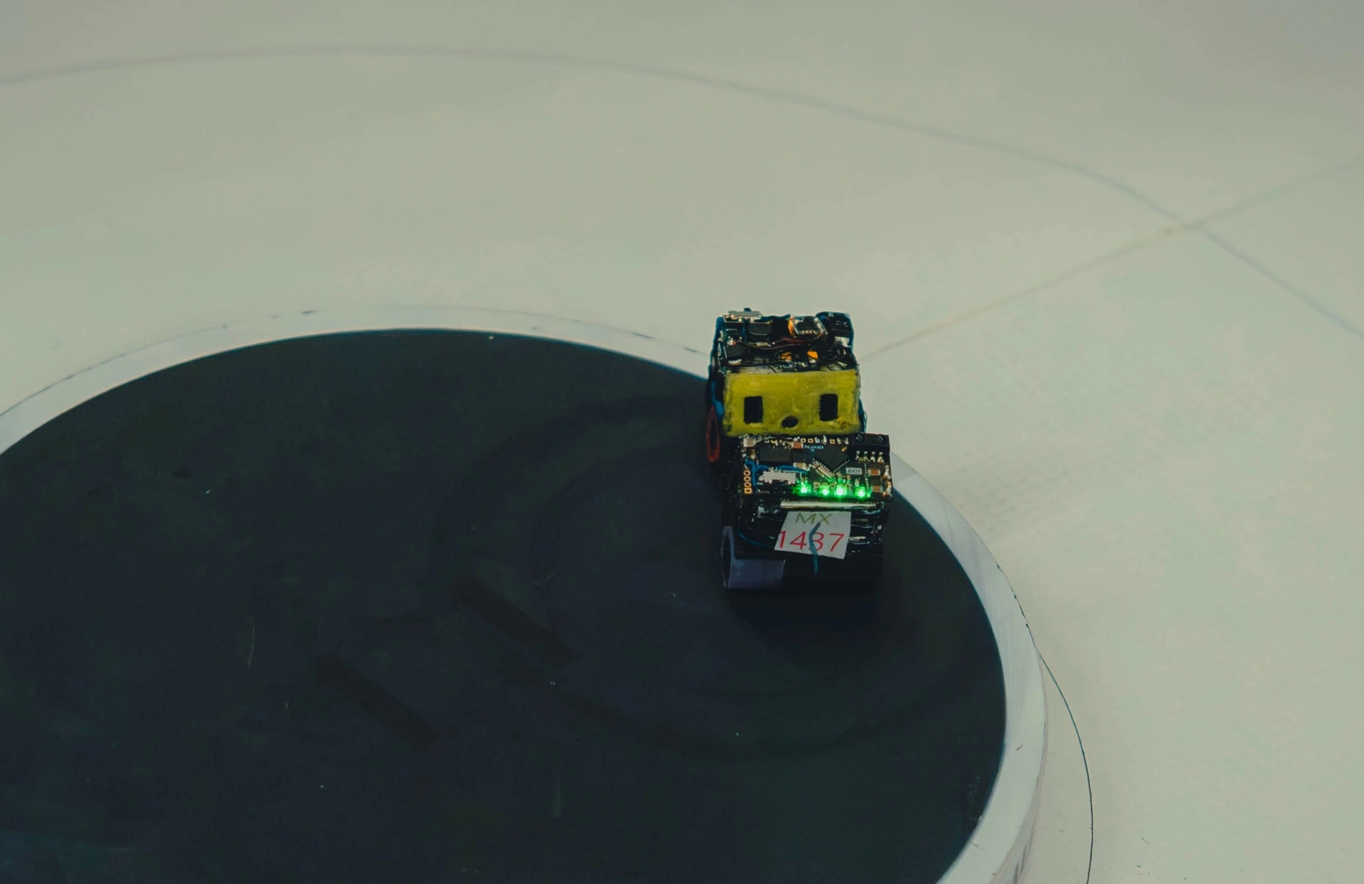
In the photo: two nano sumo robots pushing each other, RoboChallenge 2026, Bucharest. Photo: Ionescu Darius (LSE București).
Testing, inspection and safety
A practice ring: a plywood or MDF disc 19.25 cm across and 1.25 cm thick, painted matt black, with a 6.25 mm white border and 25 × 10 mm start lines.
The checklist: the 26 mm frame and height; 26 g at most (24–25 g on your scale); the A4 test; start and stop by remote ten times; the edge test from every angle, 50 times without a fall; all again on a half-empty battery.
Safety:
- A tiny LiPo is still a LiPo: charge it with a suitable charger at a low current (about 50 mA for 50 mAh), on a non-flammable surface and never unattended; retire a puffed cell.
- Keep button cells and small parts away from young children: swallowing them is dangerous.
- Soldering and reflow: use extraction or an open window, do not breathe flux fumes, wash your hands after handling paste.
- The laser cutter: never cut PVC (it releases chlorine), run the extraction for acetal, never leave a running cutter alone.
- The lathe and CNC machine: safety glasses, tied-back hair, no gloves near rotating parts; glasses when sanding wheels too.
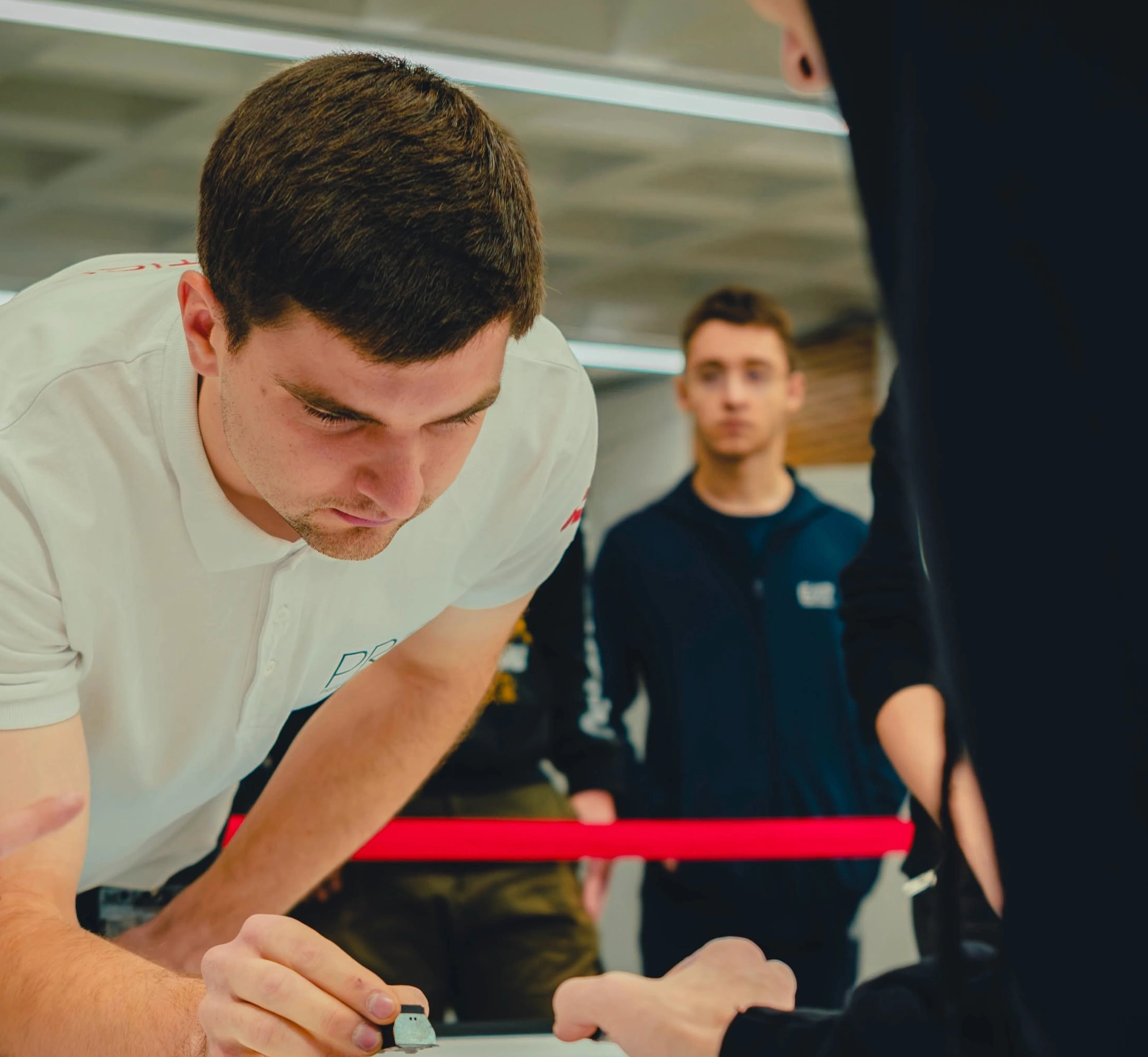
In the photo: after all the tests, a real match. A competitor places a robot on the ring, RoboChallenge 2026, Bucharest. Photo: Ionescu Darius (LSE București).

Other categories: how to build them
- Mega Sumo: how to build a 3 kg robot — a CNC frame, laser cutting, magnets and strong motors.
- Mini Sumo: a 500 g competition robot — a custom board, SMD soldering, cast tyres and a hardened blade.
- Micro Sumo: a 100 g robot — the step of miniaturisation before nano.
- A competition line follower from scratch — the sensor board, a light chassis, encoders and a suction fan.
- For beginners: a sumo robot step by step and a line follower step by step.
- Rules and champions: Mega Sumo and RageByte, Mini Sumo and Kokadama, the line follower, PID and Kavtazi.
- Combat robots: building your first combat robot.
Getting ready to compete? GRA's championships and their rules are on the competitions page; for combat robots, registration for the international ROBO BATTLE 2026–2027 is open. All our articles on this topic: the sumo tag.
Sources and videos
- Nano Sumo Regulation, RoboChallenge
- Micro Sumo Regulation, RoboChallenge
- Mini Sumo Regulation, RoboChallenge
- Mega Sumo Regulation, RoboChallenge
- Nanoroboty – koncepcja i realizacja robota nanosumo (Nanorobots: concept and realization of the nanosumo robot), Grzegorz Piecuch / JETACOMPS, 2012
- Building Small Robots: Making One Cubic Inch Micro-Sumo Robots and Smaller, mikey77 / Instructables
- Nano Sumo Robot, Patrick McCabe / Patrick McCabe Makes
- Nano Sumo Robot Takes On All Comers, Hackaday
- Skoobot, William Weiler / Hackaday.io
- Skoobot-Design (STL), William Weiler / GitHub
- Mini-Sumo-Line-Sensor, Andrei Popescu-Filimon / GitHub
- Competitions, HBFS Robotics
- FuriousPuça: Nano Sumo Robot Winner of RobotChallenge 2010 (Vienna), Ferran Gascon / YouTube
- Nano, Micro and Mini Sumo Robots at RobotChallenge Beijing 2019, HBFS Robotics / YouTube
- Nano Sumo Fighting Robot, Patrick Mccabe / YouTube
Illustrations: Grzegorz Piecuch, JETACOMPS (CC BY-SA 4.0). Photos: mikey77, Instructables (CC BY-NC-SA 4.0). Cover photo: Georgian Robotics Association, SUMO school robot competition 2024. Diagrams: GRA.