En

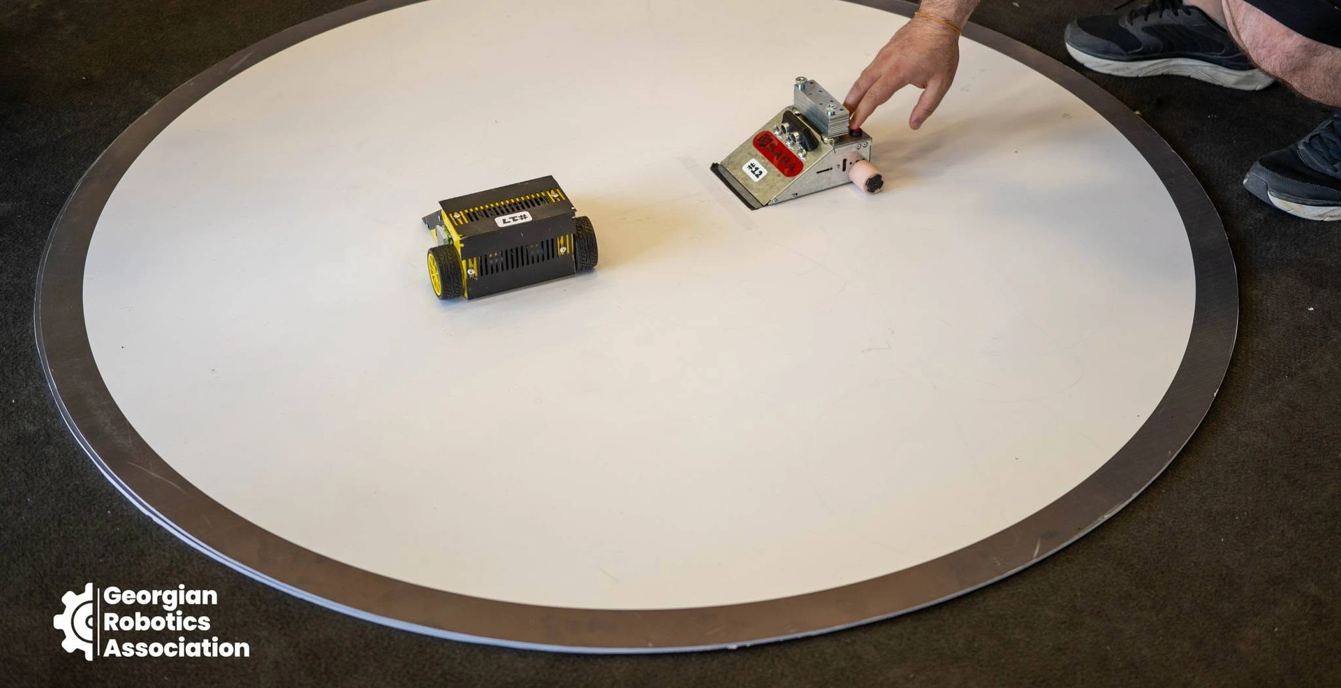
Micro sumo robot: 100 g, 5 cm and the weight classes
A micro sumo robot is robot sumo at jeweller's scale: motors, battery, sensors, board and blade in a 5 cm cube, under 100 g in all. This guide shows how experienced builders make one — PCB design and manufacture, CNC machining, laser cutting, 3D printing and cast tyres. The basics are in how to build a sumo robot, the rules and match procedure in our mini sumo article; here we are in the workshop.
The classes under the 2026 regulations of RoboChallenge in Bucharest (last changed on 8 October):
- Nano Sumo — under 25 g, a 2.5 cm cube; ring Ø 19.25 cm.
- Micro Sumo — under 100 g, a 5 cm cube; ring Ø 38.5 cm with a 12.5 mm white border.
- Mini Sumo — under 500 g, 10 × 10 cm, any height; ring Ø 77 cm.
- Mega Sumo — under 3 kg, 20 × 20 cm; a steel ring Ø 154 cm, magnets allowed.
The first diagram draws them to scale (the numbers match the list): each step down halves the ring and the robot's width and cuts the weight four- to sixfold. In micro sumo the ring is black-painted wood, fans and suction are banned, tyres must not hold an A4 sheet for over two seconds, and an infrared start/stop module is mandatory.
GRA's 2026 championship had Mini and Mega Sumo — our teams' Bucharest results are here. All four classes in one video, from Robotic Arena 2026 in Wrocław:
Design: the CAD model and a weight budget to the gram
With so little room, build the robot in CAD first. m_piotrowicz (Instructables) drew his cover in Autodesk Inventor and the electronics in KiCad; Micropanda, by the Spanish maker Javier Isabel, has an open FreeCAD body; Stratos, by KamilWu of KoNaR, the student robotics club of Wrocław University of Science and Technology, models even its gears, tyre mould and blade. Put the board into the assembly as a STEP model from KiCad to catch collisions before you order.
The motors are the hard part. A micro metal gear motor (the N20 class) is 10 × 12 mm across and about 26 mm long without its shaft: two on one axis make 52 mm, more than the robot. So builders offset them, one ahead of the axle and one behind, and drive the wheels through gears. The second diagram:
- blade;
- PCB — the floor and part of the body;
- offset motors;
- gears to a common wheel axis;
- wheels with cast tyres;
- LiPo battery;
- opponent sensors;
- edge sensors behind the blade;
- start/stop module on top;
- ballast, low and in front;
- printed or machined shell.
The third diagram is an example weight budget for a two-cell (2S) micro sumo, in rounded grams: 1 — two motors 19; 2 — board 10; 3 — battery 10; 4 — printed body 10; 5 — wheels and tyres 6; 6 — sensors and start module 4; 7 — wires and screws 4; 8 — blade 2; 9 — ballast 33. Total: 98 g.
Electronics are light, so a micro sumo usually comes out 30–40 g short: m_piotrowicz glued lead under the body with epoxy, and the PLA robot in a thesis at Ecuador's Universidad Politécnica Salesiana weighed 99.0 g. Choose ballast by density: 33 g is 1.7 cm³ of tungsten, 2.9 cm³ of lead or 4.2 cm³ of steel. Mount it low, near the blade, aim for 98–99 g (scales differ) and weigh every part on a 0.01 g scale.
Electronics: the PCB as the robot's body
In micro sumo the PCB is often the floor. Micropanda's two-layer 50 × 45 mm board carries an STM32F103, a TB6612FNG motor driver, four QRE1113 edge sensors and home-made infrared opponent sensors, with the printed body screwed on top. The first Stratos is a four-layer 42.9 × 50 mm board: an ESP32-S3 module, a DRV8210 driver per motor, two VL53L0X time-of-flight (ToF) sensors, a 38 kHz start-signal receiver and a single-cell LiPo charger.
Two layers or four? Two are enough, and cheap. Four give the inner layers to ground (GND) and power: short return paths, less motor noise at the sensors, easier routing.
Schematic blocks: power (switch, reverse-polarity protection, 3.3 V and 5 V regulators, battery voltage divider), microcontroller with programming connector, drivers, sensors, start module, buttons and LEDs. In KiCad:
- Draw the schematic and run the electrical rules check (ERC).
- Import the outline from CAD (DXF), with wheel cut-outs and mounting holes.
- Place what the mechanics dictate first — sensors, connectors, switch.
- Route power and motor traces wide, pour ground, run the DRC with your manufacturer's rules.
- Check the STEP export in CAD, then generate the Gerber and drill files.
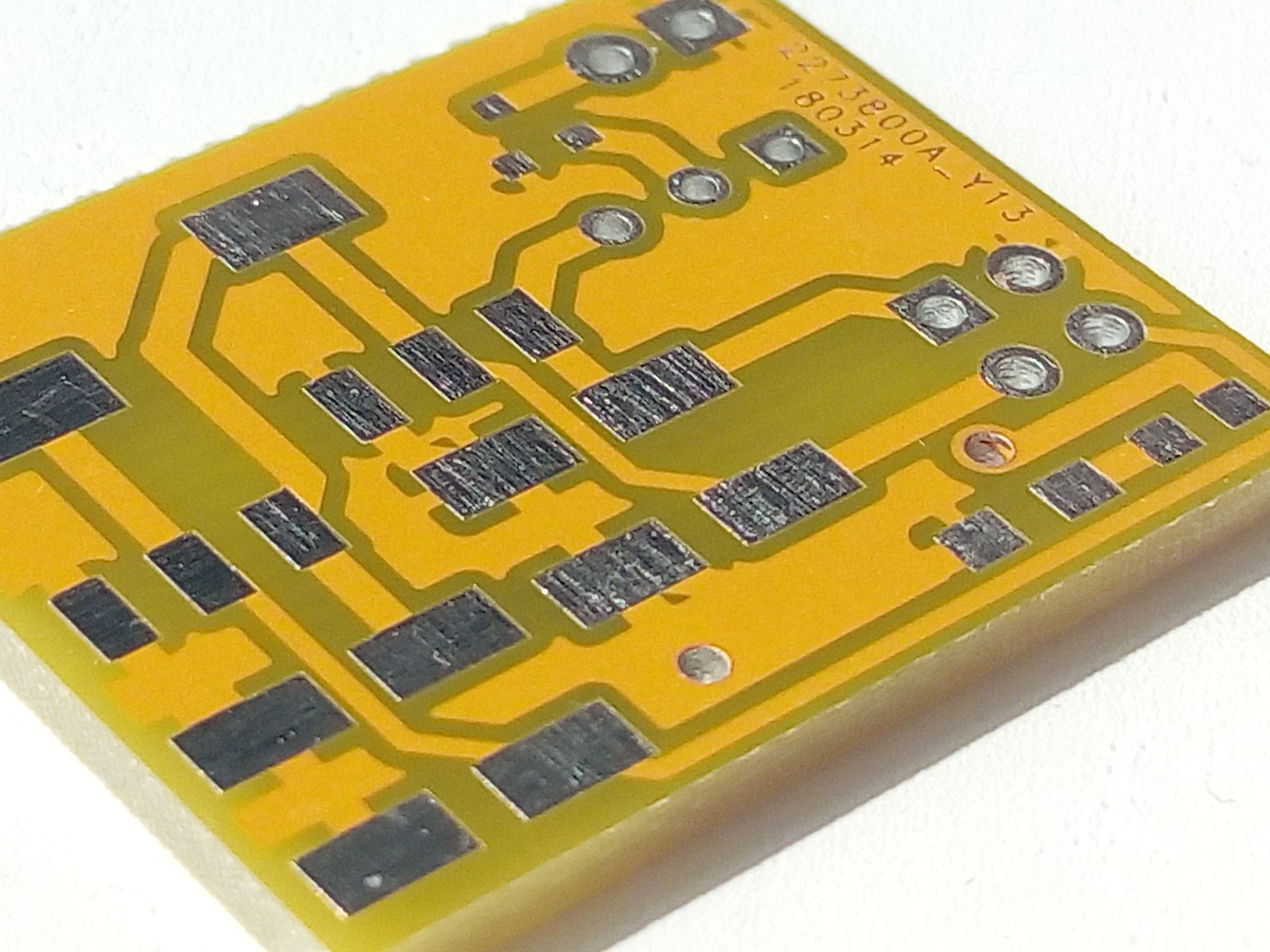
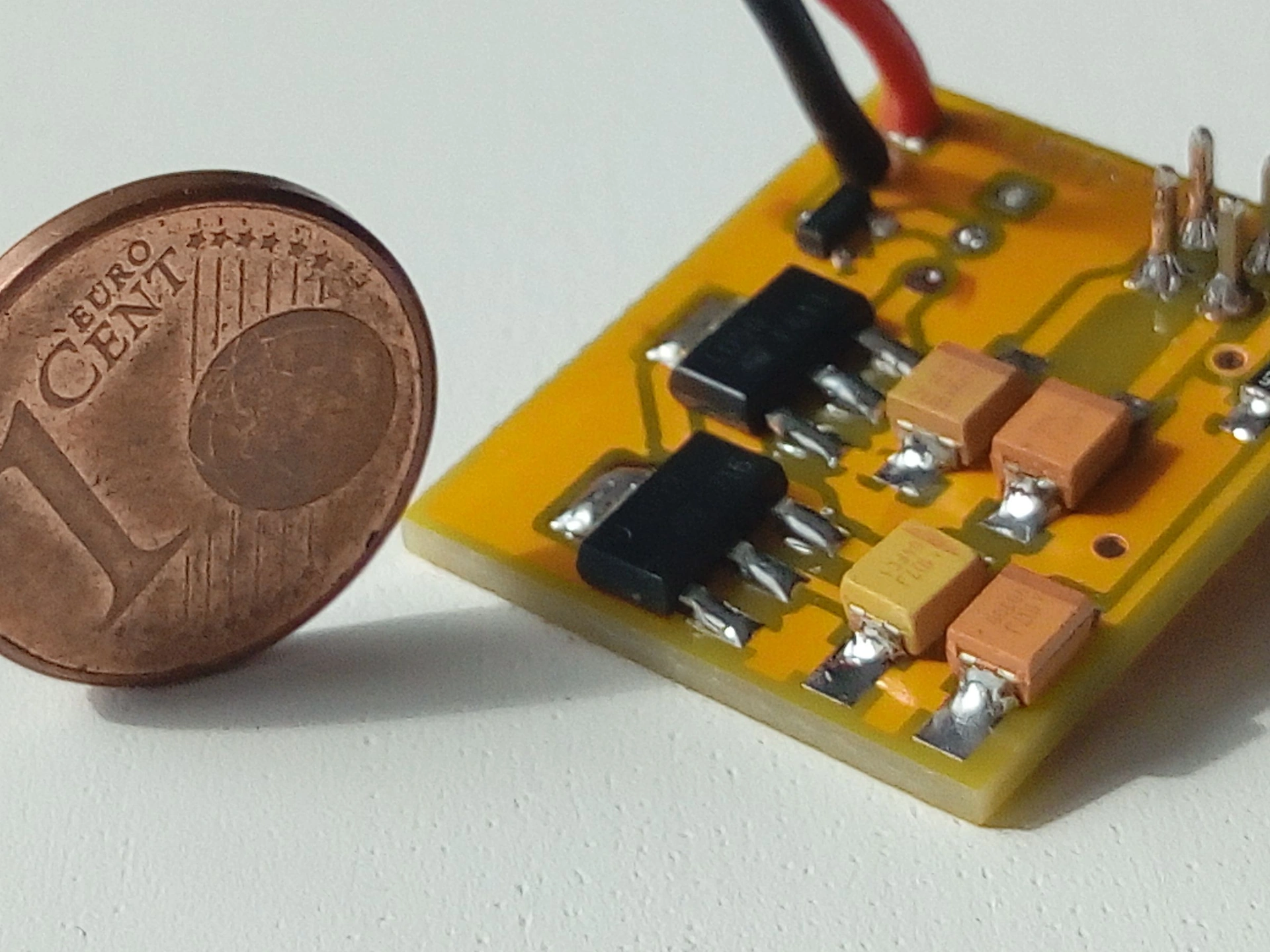
Making it. Order boards from a PCB manufacturer, or make a two-layer prototype at home by CNC isolation milling or by toner transfer and etching in ferric chloride. The photos: m_piotrowicz's board bare, then with two LM1117 regulators soldered, beside a one-euro-cent coin.
Soldering and power-up. 0603 surface-mount (SMD) parts solder by hand with a fine tip and flux; QFN packages need solder paste, a stencil and hot air or a hot plate. Check for a short between plus and ground, power up from a current-limited supply, measure the voltages, flash a blink program, then test drivers and sensors one at a time.
GALVISENPAI (in Spanish) designs a micro sumo board and assembles the robot:
Photos: m_piotrowicz, Instructables (CC BY-NC-SA 4.0)
Robot motors, gears and the battery
On good tyres (friction near 1) a 100 g robot pushes with only about 1 newton, which even a small motor delivers — so pick the gear ratio for speed and control. Speed = π × wheel diameter × revolutions per second: a 20 mm wheel at 600 rpm does about 0.63 m/s and crosses the 38.5 cm ring in roughly 0.6 s. Faster, and the robot overruns the white border before its sensors react. m_piotrowicz uses 50:1 micro gear motors on 2S.
The layouts: offset motors with gears (the second diagram); lengthwise motors turning two or four wheels through a gear train (four wheels are steadier); or 6–8 mm gear motors on the wheels directly — simple but weak, more typical of nano sumo.
The driver must survive the stall current at the real battery voltage: a dual TB6612FNG in m_piotrowicz's robot and Micropanda, one DRV8210 per motor in Stratos.
1S or 2S? 2S (7.4 V, 8.4 V full) spins 6 V motors fast; KamilWu's earlier robot Beetle runs 2S and blinks a warning below 7.5 V. 1S (3.7 V, 4.2 V full) saves grams, needs no balance lead and can charge on the board, as in the first Stratos, but needs low-voltage motors. Both of KamilWu's robots use 150 mAh packs: in a short match the C rating and weight matter more than capacity.
GALVISENPAI's first part covers small-robot mechanics and transmissions, with STL files:
The body: 3D printing, CNC machining and laser cutting
3D printing is the fastest loop: Micropanda's body, motor mount and wheels are printed, and the thesis robot is all PLA on four M2 screws. PLA is easy, PETG tougher, carbon-filled plastic stiffer (1.6 g/cm³ against PLA's 1.24). Use 0.1–0.15 mm layers, 3–4 walls and dense infill around screws; orient motor clamps so that clamping does not split the layers; print holes 0.1–0.2 mm small and drill them true. More in our 3D printing article.
CNC machining suits parts that take hits or carry mass — an aluminium, brass or steel base, side plates, motor clamps; brass and steel double as ballast. The sequence: CAD → toolpaths in a CAM program → stock in a vice or on double-sided tape → a 1–2 mm end mill → deburring.
Laser cutting: a CO2 laser cuts acrylic and plywood for prototypes, templates, the practice ring and the 51 mm check frame; a steel blade blank or a stainless plate needs a fibre laser — send a DXF file to a workshop that has one.
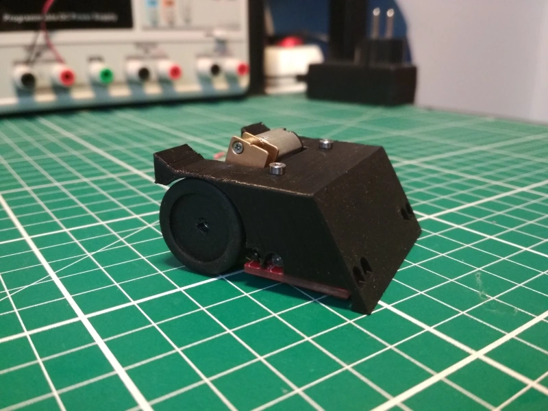
The photo shows Micropanda's printed body on its red PCB.
Photo: Javier Isabel (JavierIH), GitHub (CC BY-SA 3.0)
The blade and cast tyres
The blade decides matches: whoever gets under the other first usually wins.
- Use thin hardened spring or stainless steel, a few tenths of a millimetre thick, the robot's full width.
- Cut it with shears or a laser; drills will not go through hardened steel, so glue or clamp the blade on.
- Grind the edge at a shallow angle on a fine, water-cooled stone; steel that turns blue has lost its hardness.
- Deburr the back; mount the blade so it flexes slightly and touches the ring along its whole width.
It must not be white and must be covered off the ring (two warnings give the opponent a point).
Tyres are usually cast. m_piotrowicz cast silicone onto printed wheels; Stratos's files include a tyre mould. Erich Styger documented polyurethane casting: Shore 20, parts A and B 1:2 by weight, a printed mould, glycerine as release agent, 16 hours to cure — and a first batch that never set because it was poorly mixed. Key the tyre into grooves in the hub, give the two-part mould a vent, stir and pour slowly, and true the tyre with fine sandpaper while the motor spins it. Sticky tyres are banned (the A4 test). More on casting in the mini sumo build guide.
Sensors and the start/stop module
Opponent sensors come in two kinds: digital infrared with about 40 cm range — m_piotrowicz's Sharp GP2Y0D340K managed about 25 cm in practice; the Ecuadorian thesis and GALVISENPAI use the JS40F — and VL53L0X-type ToF sensors that measure distance (two on Stratos, four on Beetle, each given its own I2C address via its XSHUT pin; see the mini sumo article). On a 38.5 cm ring, 40 cm covers everything; tilt the sensors slightly down so they ignore the referee. The photo shows where m_piotrowicz's front and side sensors look.
Edge sensors: small QRE1113-type reflective sensors behind the blade, 1–3 mm above the ring. At 0.6 m/s the robot crosses the 12.5 mm border in about 20 ms, so read them every 2–5 ms or use a comparator and an interrupt. m_piotrowicz admits his edge sensors failed in testing — plan their place from the start.
The start/stop module is mandatory. RoboChallenge's has four pins — VCC, GND, Start and Kill: Start goes from 0 to 1 on start and back to 0 on stop, Kill drops from 1 to 0 on stop, and the green LED must be off at power-on. To save space, leave a small connector for the module or, like Stratos, fit your own 38 kHz receiver and decode the RC-5 commands in firmware (codes in our sumo robot guide; check the organiser's appendix). Mount it on top.
Photo: m_piotrowicz, Instructables (CC BY-NC-SA 4.0)
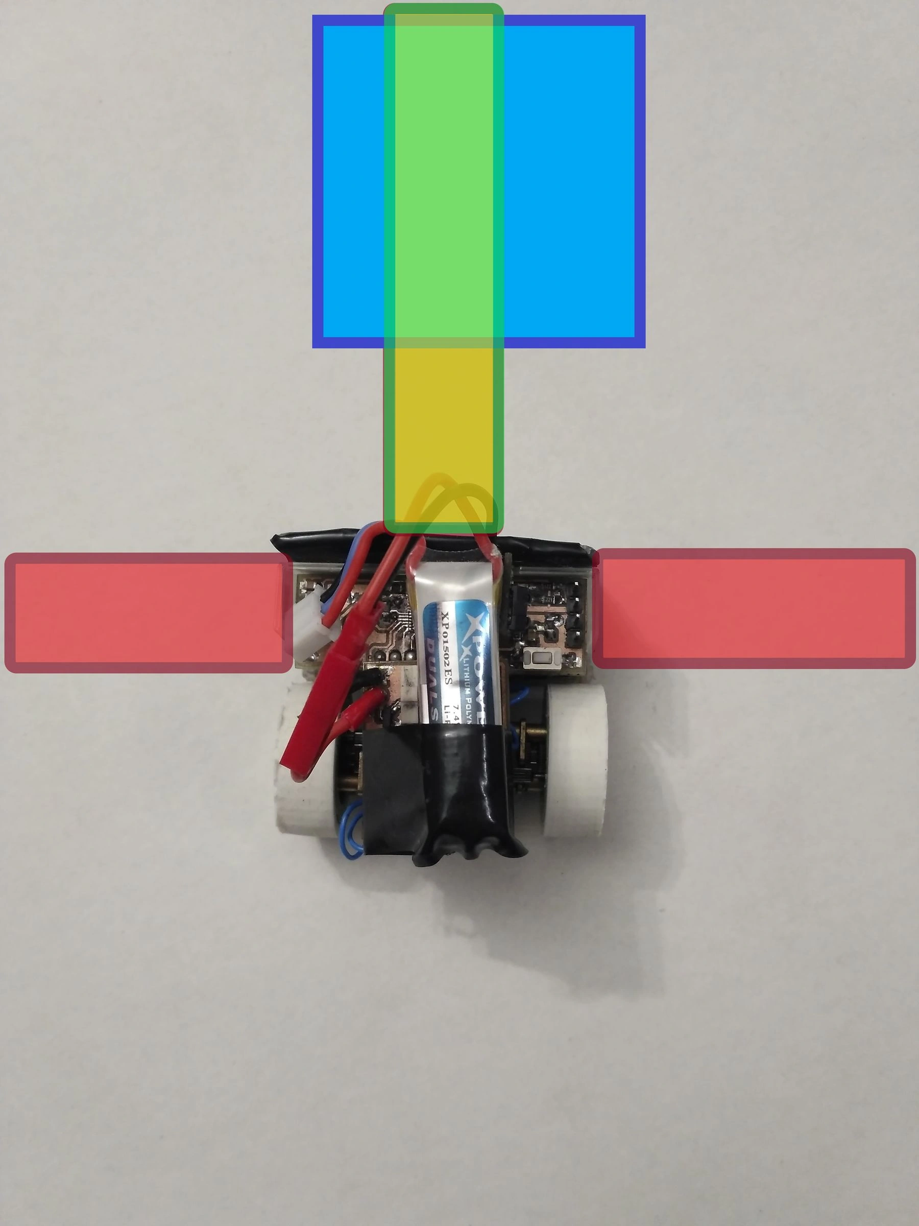
Micro sumo robot assembly, step by step
- Test prints — fit the body and mounts to the real motors, battery and board.
- The board — install it only when soldered and tested.
- Motors and gears — set the gear mesh with a strip of paper; both wheels must spin freely.
- Wheels — on a flat plate, both wheels and the blade edge touch the surface.
- The blade — look against the light: no gap anywhere.
- Sensors — check the readings in the serial monitor.
- The battery — held firmly, safe from the blade and screws; connector and switch reachable.
- Ballast — weigh, add it low and forward, fix it with epoxy.
- Dimensions — a home-made 51 mm bottomless frame; under 51 mm tall; 98–99 g.
- Number and blade cover.
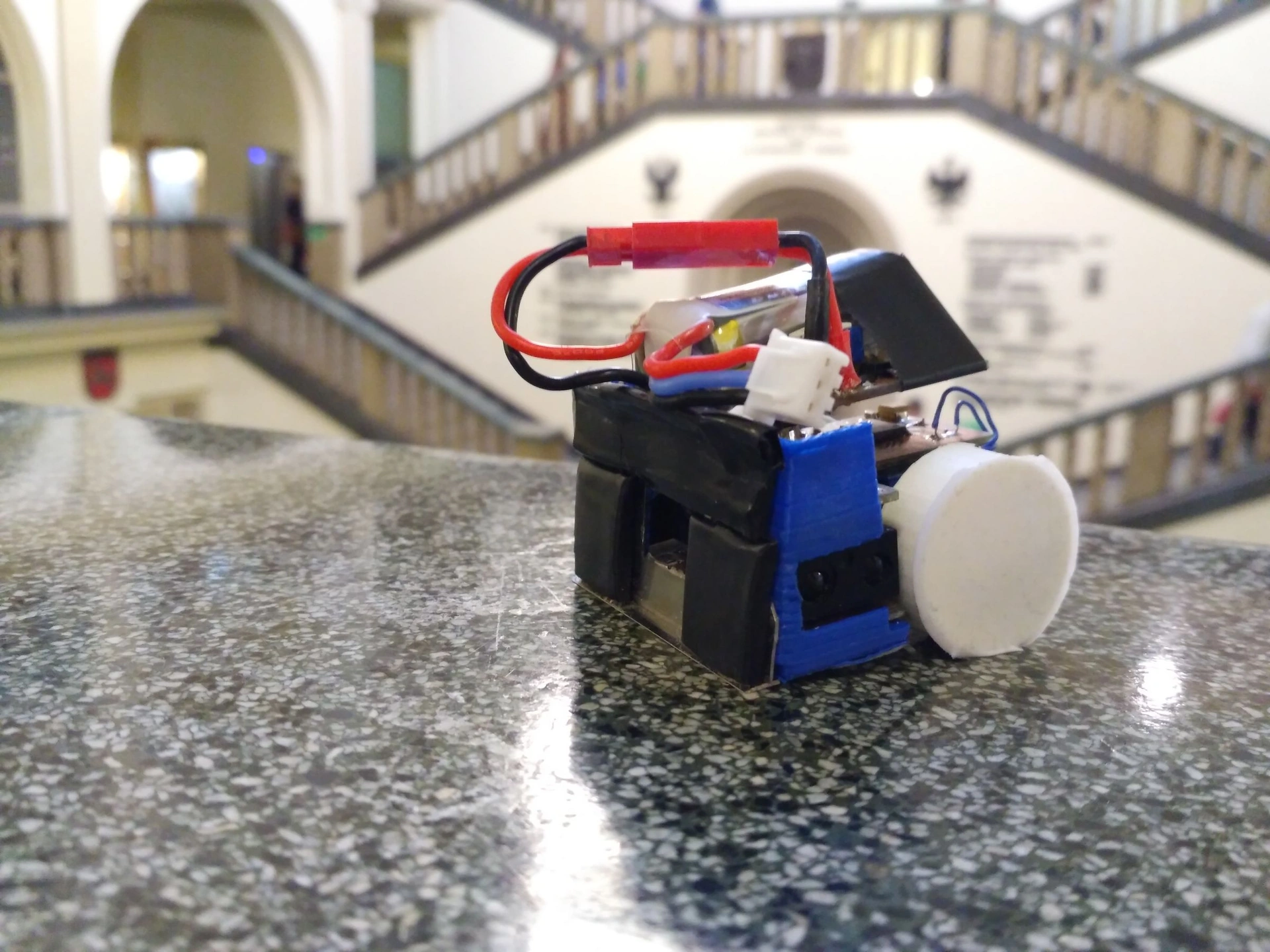
Photo: m_piotrowicz, Instructables (CC BY-NC-SA 4.0)
Programming, testing and homologation
The state machine (wait, search, attack, escape the edge) is in our sumo robot guide. Micro sumo adds:
- The start decides a lot. On a small ring the robots start close. Pre-program several openings (straight attack, side-step, turn on the spot) and choose one between rounds with a button or DIP switch — Stratos has both, Beetle two switches; RoboChallenge allows up to a minute between rounds.
- Loop order: start/stop and the edge first, then the opponent; ramp up the power to avoid wheelspin; check the battery at power-on.
- Flags: KamilWu calls Stratos a "micro sumo robot with flags" — panels that unfold after the start to confuse sensors. Unfolding is allowed if the robot stays in one piece; active jamming is banned.
Testing: a 38.5 cm, 1.25 cm-thick plywood or MDF ring, matt black, with a 12.5 mm white border. Fifty edge runs from every angle, then a 100 g dummy, a half-empty battery and different lighting.
Homologation (RoboChallenge Micro Sumo), at the group start and before every match: a visible number (photographed at the group start), a bottomless 51 mm frame, under 51 mm tall, at most 101 g on the scale, start and stop with the referee's remote, the blade covered, the same operator.
Workshop safety
- LiPo: no shorts on the tiny connectors; balance charger (2S) or on-board charger (1S), on a non-flammable surface, never unattended; retire swollen packs.
- Soldering: extract the flux fumes, wear glasses, wash your hands.
- Etching: ferric chloride is corrosive — gloves, glasses, plastic tubs, never down the drain. Keep FR-4 glass-fibre dust wet or vacuum it; wear a mask.
- CNC: glasses, clamped stock, hands clear; no loose sleeves or gloves.
- Laser: never unattended, extraction on, never cut PVC or vinyl (chlorine).
- Casting: polyurethane contains isocyanates — gloves and ventilation.
- Blade: glasses when grinding; keep it covered.
- Lead is toxic: seal it in epoxy, wash your hands, adults only; tungsten or steel is safer.
Other categories: how to build them
- Mega sumo robot build — 3 kg, 20 × 20 cm: a CNC frame, laser cutting, magnets.
- Mini sumo robot build — 500 g, 10 × 10 cm: the PCB as the chassis, SMD soldering, cast tyres.
- Nano sumo robot — 25 g, a 2.5 cm cube: the smallest motors and controllers.
- Pro line follower build — a sensor-bar PCB, motors with encoders, a fan for the Turbo class.
Beginners and rules: sumo robot step by step, line follower step by step, Mega Sumo, Mini Sumo, line follower and PID; combat robots — your first combat robot.
Getting ready to compete? GRA's championships and their rules are on the competitions page; for combat robots, registration for the international ROBO BATTLE 2026–2027 is open. All our articles on this topic: the sumo tag.
Sources and videos
- Micro Sumo Regulation, RoboChallenge
- Nano Sumo Regulation, RoboChallenge
- Mini Sumo Regulation, RoboChallenge
- Mega Sumo 3kg (auto) Regulation, RoboChallenge
- MicroSumo (100g) Competition Robot, m_piotrowicz / Instructables
- Micropanda: microsumo robot (hardware, 3D, firmware), Javier Isabel / GitHub
- Stratos: MicroSumo robot with flags, KamilWu (KoNaR) / GitHub
- Beetle: a microSumo robot, KamilWu / GitHub
- Desarrollo de robot micro sumo autónomo para competencias de robótica profesional, Derian Guevara / Universidad Politécnica Salesiana, 2025
- Making Perfect Sticky DIY Sumo Robot Tires, Erich Styger / MCU on Eclipse
- MICROSUMO | TUTORIAL PARTE 1 (video), GALVISENPAI / YouTube
- MICROSUMO | PARTE 2 | PCB & MONTAJE (video), GALVISENPAI / YouTube
- Robotic Arena Wrocław 2026 - Nano Sumo, Micro Sumo, Mini Sumo, Sumo (video), SimeonBotics / YouTube
- RoboChallenge Romania 2025 - Mini Sumo, Micro Sumo (video), SimeonBotics / YouTube
Photos: m_piotrowicz, Instructables (CC BY-NC-SA 4.0); Javier Isabel (JavierIH), GitHub (CC BY-SA 3.0). Cover photo: Georgian Robotics Association, SUMO school robot competition 2024. Diagrams: GRA.